Stereo amplifier transformer power supply - old dead transformer power supply


1000VA -  4 times 250VA with  4 times 28V and 4 times 9A

It would be quite safe an beautiful ring core transformer for a great audio amplifier, yes. 

Features:

  • huge and very strong, lower barycenter and a good road holding

  • much power

  • hardly break down

  • under normal operating condition very high reliability

  • cost efficient

There is something to be said against:

  • did you ever checked the primary current peaks?

  • primary current peak monstrous as the transformer self, bad for every electricity supplier

  • cause high harmonic distortion in the primary current

  • heavy, voluminous

  • electromagnetic stray field (also with a ring core)

  • needs big transformer rectifier

  • high capacity on secondary side required

  • critical in the moment when the circiut closed

  • variations of primary voltage affect the secondary side

If all these aspects are uninterested for your application, whatever the reason, then the transformer is a optimal and minimum cost solution . But, if only one listed point is a problem for you, dilemmas starts. I've tried to find a solution for some of these problems, the transformer you see is the consecuence.

deutsch deutsch english

Transformer_Frontview.JPG (23526 Byte)

Transformer_Topview.JPG (29375 Byte)

Transformer_Sideview.JPG (24399 Byte)

Pleasing to your audio eyes the 4*30.000µF transformer capacity. The bigger the capacity so much worse the peak in the primary current, however a decresaed secondary voltage ripple.

On the right side rectifiers mounted on a refrigerant aluminium angle. Ring core stands in a metal  attachment. On the sides protection circiuts.

Demonstrates the protection circiuts for overcurrent on primary, among the soft start current limitation and the input voltage monitoring.

Transformer_Topview_Fisheye.JPG (20216 Byte)

transformer_schematic_one.gif (26295 Byte)

transformer_schematic_two.gif (20055 Byte)

Thank you my 16mm fisheye objective - results in a drastic view.  

The ears on the right and left side are controlled mosfet switches of the secondary side. They switch on after receiving an ok from the secondary voltage monitoring.

Schematic part 1. It's a scan of a simplified schematic taken from a beginning of the project. Shows voltage regulators for a helper circiut and the soft start circiut. The starting procedure is not controlled, takes place by time steering.

Schematic part 2 demonstrates the actuating antiparallel mosfet's elements, used for a slowly increasing of the primary voltage. Both mosfet's are highly endangerd during the moment of switching on. In particular, if there is a load at the output. It's a aspect against this circiut, an additional protection circiut should be implemented.

transformer_Zeichnung_Strom.gif (6334 Byte)

The little sketch is mirrod in my eyes the biggest problem with enormous transformers and large capacities needed for an unimpressiv DC voltage on the secondary side. Works, but at what price, the debacle on the sketch is drawn yet harmless, at a full load the peak reach alarming current  proportions on the primäry side and in the rectifiers. These peaks generate high harmonics and a high electromagnetic emmission all over the air, they disturbe a lot the ambiance - think about it.


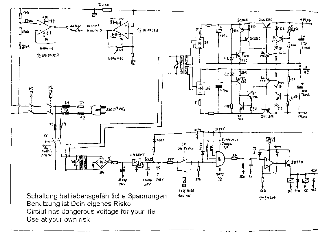
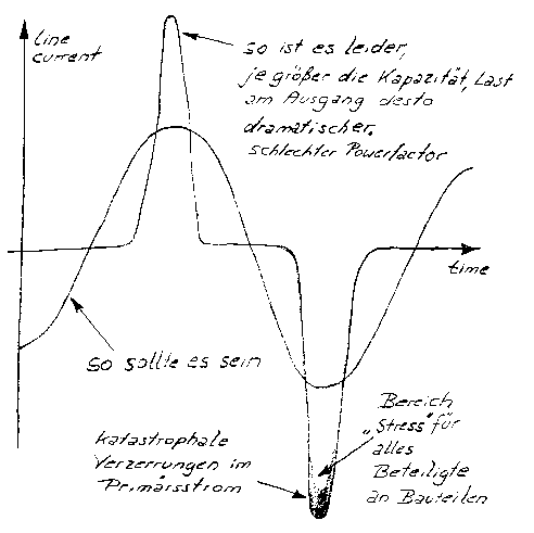
Summary: the problem of peak primary current lets damp down, but not completely solved thru a passive sine choke in the primary circiut. Note this choke will be large and expensive for such a big transformer and high capacitiy, where's got the advantage? All the other problems like voltage 
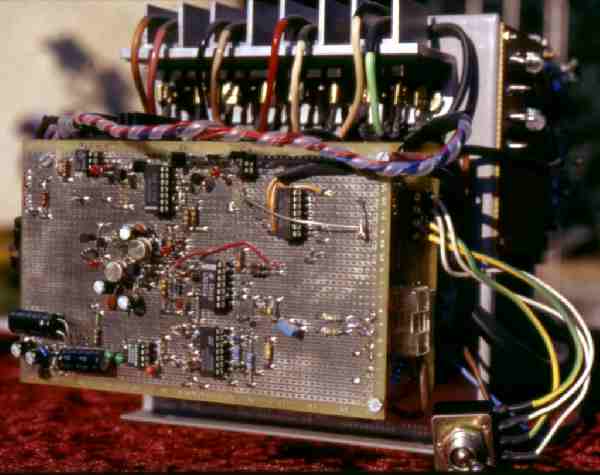
monitoring, timing, current monitoring etc. can be sold be circiutry, although their amount to go beyond the scope.

Nasty to solve is the problem of the electromagnetic emission, the whole huge power supply should be integrated in a faraday cage, the greater all parts the bigger and more expensive your cage, that's a despiteful fact.

Another fact: already thougth about that these monstrous transformers having a high capacity between primäry and secondary side? In particular at higher frequencies the wished galvanic coupling changes to a capacitive coupling.

Stupidly most interfering signal are of high frequent character, they transmitt very easy their 
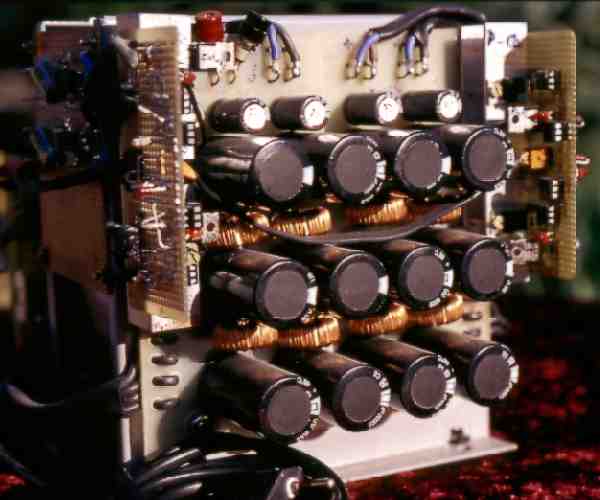
energy by this path.Yes, there is a big electrolytic block downstreamed (can't reject highfrequency) and some few ceramic capacitors. They dont help much, with an increasing load the cut off frequency increase similary. You could elaborate this filter through a huge number of expensive ceramic capacitors, it will be very expensive.

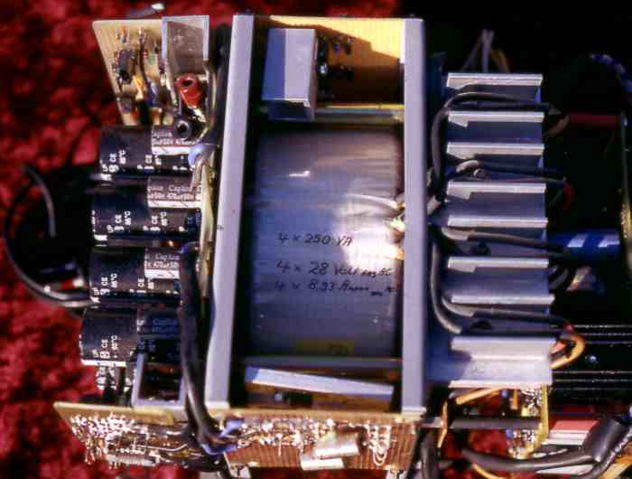
There are quality big transformers with a metallic shielding winding between primary and secondary to reduce the capacitive coupling, however for a quality price.

The word shielding is used wrong, it would be a magnetic short circiut, so at least at one point the shielding must be open and at this area and the border areas also a coupling exists. That's the the art and knowledge of  transformer manufactorers to seperate the wheat from the chaff.

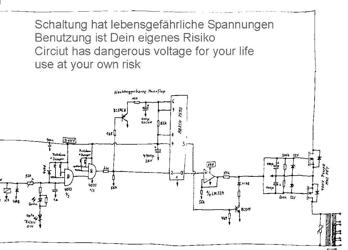
Outlook: what's next? A new design is momentary under construction. I've knewed before I've started that this power supply will have large primary peaks and I didn't cared about. For a preliminary version no matter. But the remaining aspects like timing, starting, switching on and off changed the project in big task and dimensions. (the showed schematics are only the half of it, I don't want to bore you). This thing has taken me enough hours of my life - to give everything a sense, I'll build up a labority power supply with it.

www.amplifier.cd

Contact and Disclaimer