"what can you do
with this thing?"
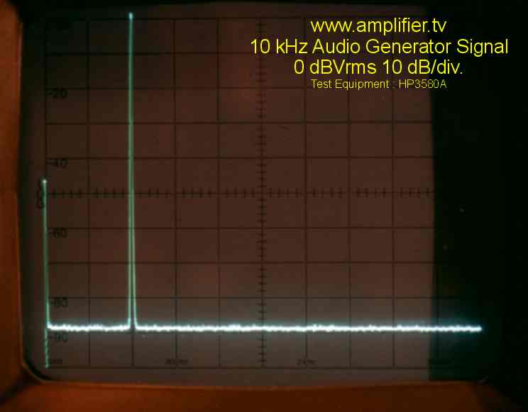
For a measurement THD + noise + other distortion, the
source contains still some little mixing products and is a little noisy
near DC. But an excellent source to measure harmonic distortion, it
is curently the best source I use. Very
good to measure nonlinearities of digital to analog converters or
amplifiers. Top application is distortion measurement with audio
amplifiers. Which audio amplifier do not like a pure sine like this.
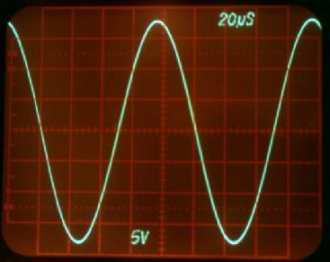
"high open loop
cause also problems"
A circiut with such a high
open loop makes it more and more difficult to control the amplitude, the designer did already an
excellent work with the amplitude control circiut. Only a very small uncontrolled errorsignal could be
enough and the outputs responds with clipping.
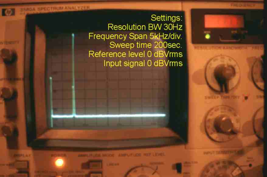
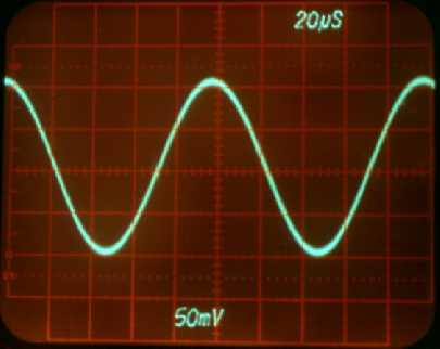
A amplitude modulation e.g. caused by the amplitude control seen on the
analyzer as two little lines close to the carrier and close to DC. The
modulation frequency of the amplitude control circiut seen as delta
frequency between mixing products and the carrier or DC. For most
analyzers and also many FFT analyzers it is difficult to show such details. Many distortion measurement brigdes and audio analyzers,
their build in tuneable filters are not sharp enough measuring such details. They can't measure these
distortions very close to the carrier, due too high filterbandwidth, the instruments "think"
these distortions are part of the signal. As result their displayed THD + noise + other distortion
measurement result is lower than in reality. The high open loop gain leads to a high sensitivity for
external signals. This super gain block amplifier takes his job very seriously, every signal on the inputs will be
powerfull amplificated.
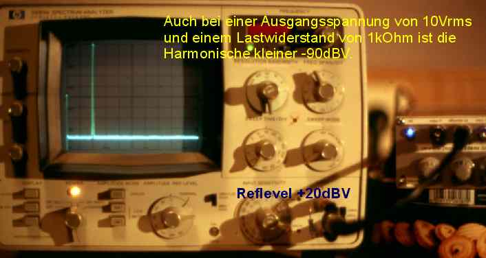
Now you understand,
why I have done such enormous investigations in shielding and powersupply, it is necessary to keep the noise + other
distortions as low as possible.
"what's
going on?"
Of course it would be very nice to push more gain and
performance to the circiut, but for what? You really want to reduce the harmonics more? Can you measure it? It makes
no sense, no audio amplifier reaches such a low distortion level. Ok, perhaps some special measurement amplifiers.
Yes, to design a better amplitude control, a good idea. I've never try it,
but I think it is not an easy task and takes much time to get a better
result, the current amplitude control is already very good. If
somebody have a good idea, please contact me.
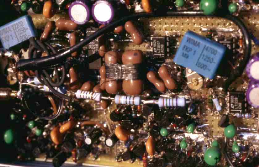
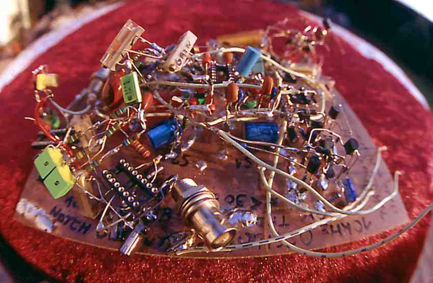
One issue could be getting a better stability frequency vs. temperature.
I tried to compensate the time constant of the Wien Bridge. I reached a
stability of 10,000 Hz +/-3Hz over a temperatur delta of 30 Fahrenheit,
that was enough for me, I will not use the generator in a desert, arctic
or in a nordic sauna. The visible wires wrapped around the big brown
capacitor are resistor wires as heater. I designed a phase lock loop
with heater and a controlled fan above the capacitor for cooling. I used
a lot of time to run the control. A work with many parts and
investigations. Another bad aspect, I saw the fan's influence on the
spectrum. I closed the project. Another method could be a oven or a
peltier element. But really no - for what - you really think it makes a
different to measure the distortion at 9995 Hz or 10005 Hz? Stop this
nonsens, don't try it, go and make better
a nice amplifier, more gain for you, and the amp don't
make always the same sound.
"the search for a pure sine is a never ending story"