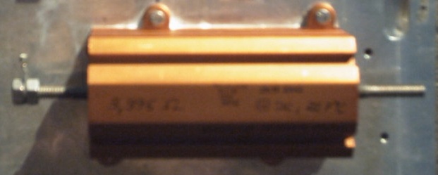
Audio Load Resistor with 4 OhmThe report concerns itself with the measurement of the frequency response of a 4 ohms load resistance for audio amplifier. |
|
For measurements of audio amplifiers are accomplished a multiplicity of measurements under load. The load amounts in many cases four ohms or eight ohms. For some measurements e.g. also capacities can be connected parallel. Most measurements happen under load, e.g. amplitudes and phase responses or distortion factor measurements. |
Requirements of the load resistanceSufficient size, in order to be able to exhaust problem-free the developing heat dissipation. The heat dissipation should be not a problem for a longer period, e.g.. 1 hour, that is useful for stress-free measuring. Tthe heating up should change the resistance value only insignificantly. The largest requirement is as constant a frequency response as possible over all tested audio frequencies. A few hundred kHz are a good starting position. Also the phase response should be as constant as possible. Best resistances for this would be e.g.. 1 or 2 Watt of metal film resistors or bulk foil (unaffordable expensive for this application). A multiplicity of such resistances should be interconnected in such a way that the energy dissipation can be exhausted. This construction would be a quite complex special's building out approx.. 100 - 200 individual resistances. A simple solution are wirewound resistors. A suitable sent wound wirewound resistor is for many measurements a good solution. For this several types are to be tried. The manufacturers indicate rarely a frequency response for wirewound resistors. This resistances have advantages, like high overload capacity without irreversive damage, small temperature dependence and the possibility of the thermal coupling to a heat sink. Measurement amplitudes and phase responseAs basis serves a series connection from a resistance with the load resistance. The resistance works as current shunt. For the measurement is assumed the wirewound resistor under smaller and under high load behaves similarly. Therefore a simple frequency generator is sufficient as source. As series resistor can be used for example 50 ohms. Used Test Equipment Frequency Generator HP 3325A. Meter for resistance measurement HP 3457A. Gain Phase Meter HP 3575A and an additional 50 Ohm resistor. Execution of the measurement Common ground of the circuit to a side of the load resistance and to the ground of the generator. The 50 ohms resistance between the load resistance and the output of the generator. Channel A of the HP3575A at the load resistance and channel B to the generator. Provide a mathematical equation of this series connection and solve it on after the amount and phase of the load resistance. The circuit supplied with a constant amplitude of 2.76 V. Initially measurements Measured resistance 4 ohms of the load resistance with 21°C ambient exactly to 3.966 ohms of measurements resistance 50 ohms of the resistance in series exactly to 50.1 ohms. |