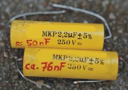
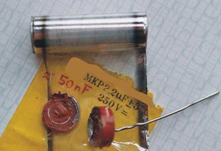
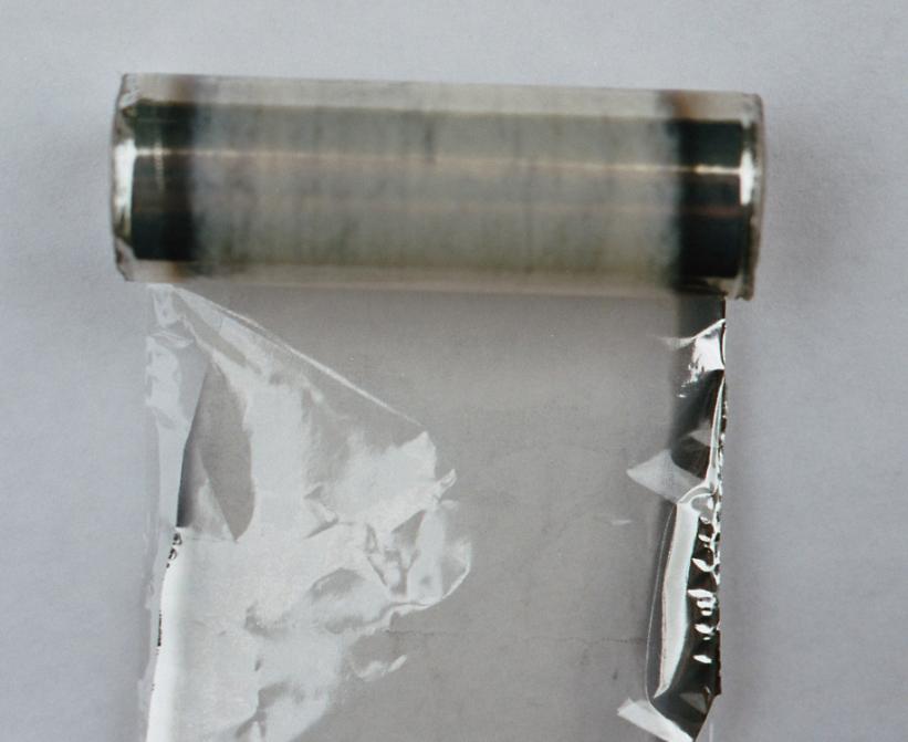
failed foil capacitor from a speaker cross over network

A capacitor with a loss in capacity from original 2.2µF to only 50nF. Resulting in a poor tweeter functionality.

Application:

the capacitor used in a cross over network for an ACR Fostex Loudspeaker, a folded exponential horn speaker BK202. The foilcapacitor of 2.2µF/250V functioned as AC coupling in the high pass filter for the ACR T825 horntweeter.

At first glance I thought the tweeter has finished with life, almost no sound comes out. Who think's first about an failed coupling capacitor. A measurement on the tweeter terminals with an oscilloscope shown at once, only some poor millivolts even with a wide open amplifier volume. Error must be somewhere between amplifier and terminals.


Note: don't think the tweeter is bad, it's the capacitor blame. The capacitor was of a bad quality, a capacitor of this size/volume and working voltage should be strong enough to easily widhstands with the tweeter currents. The midrange speaker is an ACR Fostex FD600 with an massive nut wooden horn. The woofer an ACR Fostex FW250 with the BK202 horn.

failed foil capacitors with high loss in capacitance

Figure 1 shows both failed capacitors, one in the left channel the other in the right channel. Both of them having an enormous loss in capacity, from nominal 2.2µF to 50nF and 76nF after 18 years since speaker manufactoring. The capacitance measurement done with a HP4282A at 120 Hz.


Capacitor with removed terminals

in the middle the missing aluminium


Figure 2 shows the removed leaded wires. The wires were fixed very well with a good electrical contact.

Figure 3 opened capacitor in detail. Easy to see the disappeared aluminium in the middle part of the foil.

Background

The speakers were bought as DIY kit at the end of the eighties. Also the cross over network was "the proud" of the seller: "selected parts of highest quality, well designed and selected for the speakers". Yes, it could be - but that coupling capacitor wasn't that thing he promised. No problem it's life. The other parts are:

  • cement standard wirewounded resistors

  • standard air inductor for the woofer network

  • standard air inductor for the midrange network

  • bipolarer electrolyt capacitor 22µF

  • eg.

Cross Over Network Schematic

Of course the network were rengineered to get the schematic. A simulation with Pspice.

Schematic of the crossover network for a Fostex BK202 horn loudspeaker

Figure 5 shows the network schematic with failed capacitor C1. Every speakers nominal impedance of 8 ohms.

speaker crossover networkfrequency response (amplitude)

speaker crossover networkfrequency response (phase)

shows the frequency response of the load impedance, caused by the network parts

Figure 6 shows the amplitude response from network of fig. 5

Figure 7 shows the phase response of the network in Fig. 5

Figure 8 shows the load impedance. Only the network parts changing the ideal load iompedance. With an active design the impedance would be constant, of course only if the speaker itselfs had a constant impedance, that's of course never the case.

If you havbe me a better schematic for this speaker combination, I would be very happy to receive your feedback.

Influence on sound?

The loss of the capacitance leds to much loss in high frequency audioble tones.

Schemtic in comparison Correct-Failed

direct comparison, much loss in higher frequency audioble tones

Figure 9 Schematic with failed capacitor Figure 10 amplitude response in direct comparison, the treble loss is much.

The other parts are still ok after 20 years:

  • C2 instead of 15µF remaining 14,82µF (MKT efko)

  • C3 instead of 33µF remaining 33,58µF (MKT efko)

  • C4 instead of 15µF remaining 14,85µF (bipolarer Elko glatt Roederstein)

  • all dissipation factors, ESR and leakage currents ok

  • all resistors still ok

  • all inductors ok

How could this capacitance loss happens?

Really I don't know:

  • the metallisation of the foil is very very thin. The currents into the tweeter burned out the metal, caused by heat dissipation. This theory is supported because on the foil end (terminals) there is still much metal. This border areas are better cooled by the leads.

  • diffusion of the very thin aluminium into the foil, because of the different strength (thin metallisation compared to thick plastic foil) the aluminium can be looking like dirty glass.

  • diffusion of metal to the terminal thru electro chemical effects.

  • a small hungry aluminium eater! Message of a highly decorated retired doctor of physics, no idea.

If you know how this could happens tell me

Die Moral von der Geschicht? Sense of this story?

Check also your network if something's wrong with your speaker.

Why this technical note?

such a loss capacitance is for a foil capacitor not normal at all. For some readers it is interesting to see what can happens in the electronic. These things are that things people would tell you are crazy if you tell them this will happens in future with the capacitor.

Contact and Disclaimer

www.amplifier.cd        Application Notes