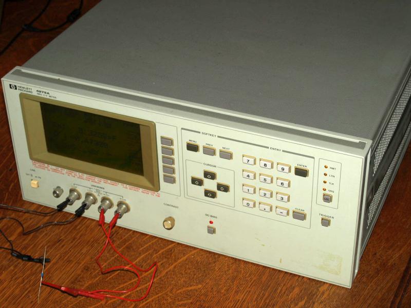
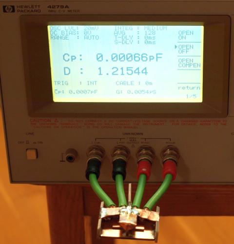
HP 4279A 1MHz C-V Meter
Ein
Kapazitätsmessgerät mit Messbereichen von 2pF (Full Scale)
bis 1nF (Full Scale). Die Besonderheit ist die hohe Genauigkeit
und Auflösung für kleine Kapazitätsbereiche und die
Möglichkeit zu messen mit einer einstellbaren Gleichspannung
überlagert.
Meter for measuring semiconductors, wafer, capacitors and other passive parts Capacitance vs. DC.
|
|
C-V instrument should be in very lab. A hardware and circuit designer should use an C-V meter.
Long list - many parts can be measured, simplifies hardware design.
Nützliches Instrument für die Entwicklung von Schaltungstechnik. |
| High Resolution measurement |
| easy to operate |
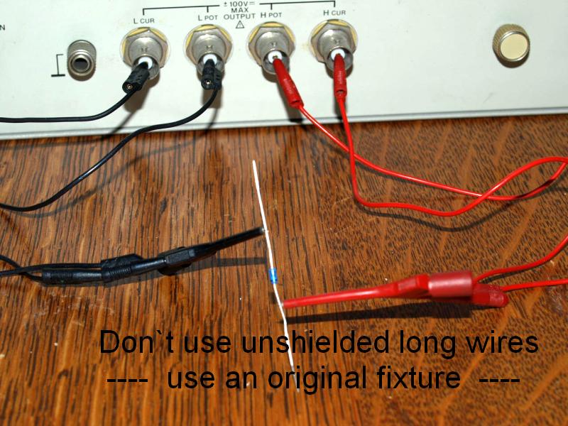
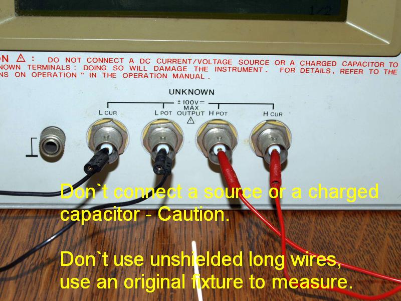
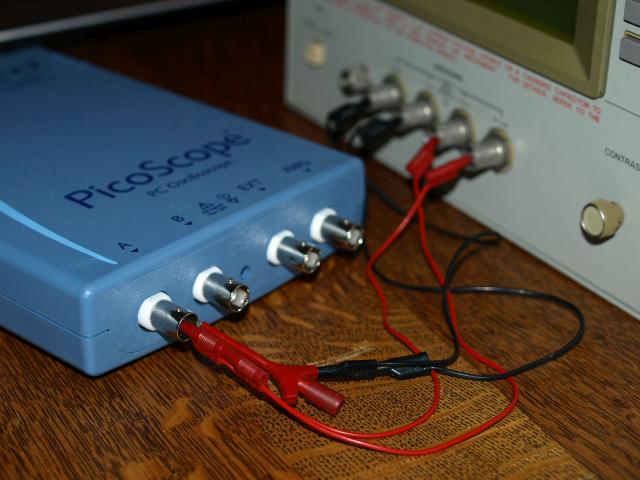
| Measuring
with these unshielded wires cause a measurement error of approx. 1pF-2pF, not
a good idea for the lowest range. There are original fixture available
with extension BNC-cables or a fixture to test SMT parts. I have to
look for a fixture. The operating manual describes in detail the principle of a good shielded fixture, read it.
|
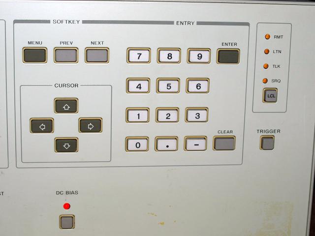
writing a GPIB program the instrument can be converted from C-V Meter to C-V Plotter
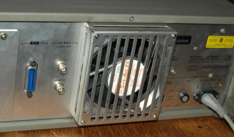
not a loud fan
Measurement Examples
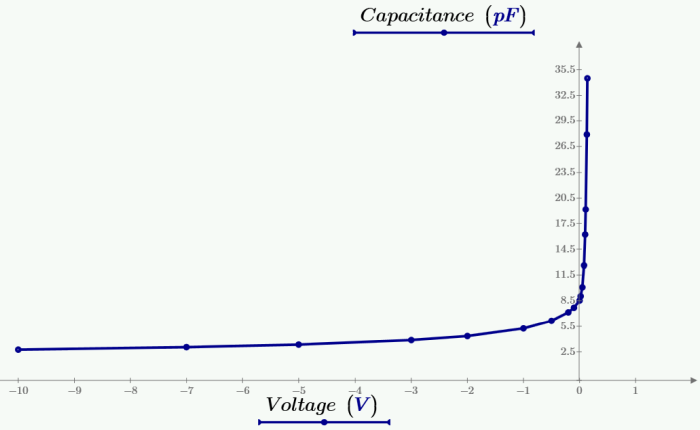
schottky diode 1N5711
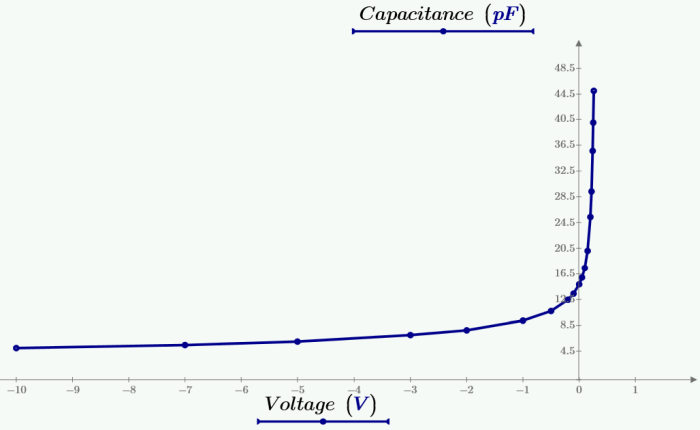
silicon diode 1N4007
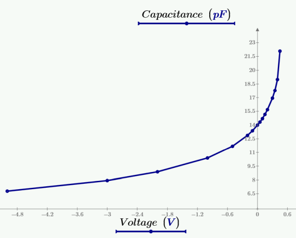
PNP bipolar Transistor 2SA1391 - (Emitter to Basis, Collector open)
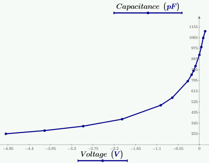
Power Schottky DSEP15-06
Input capacitance of a computer-scope input channel
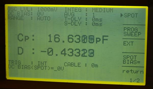
shows a litte 1-2pF higher value, due the unshielded cable.
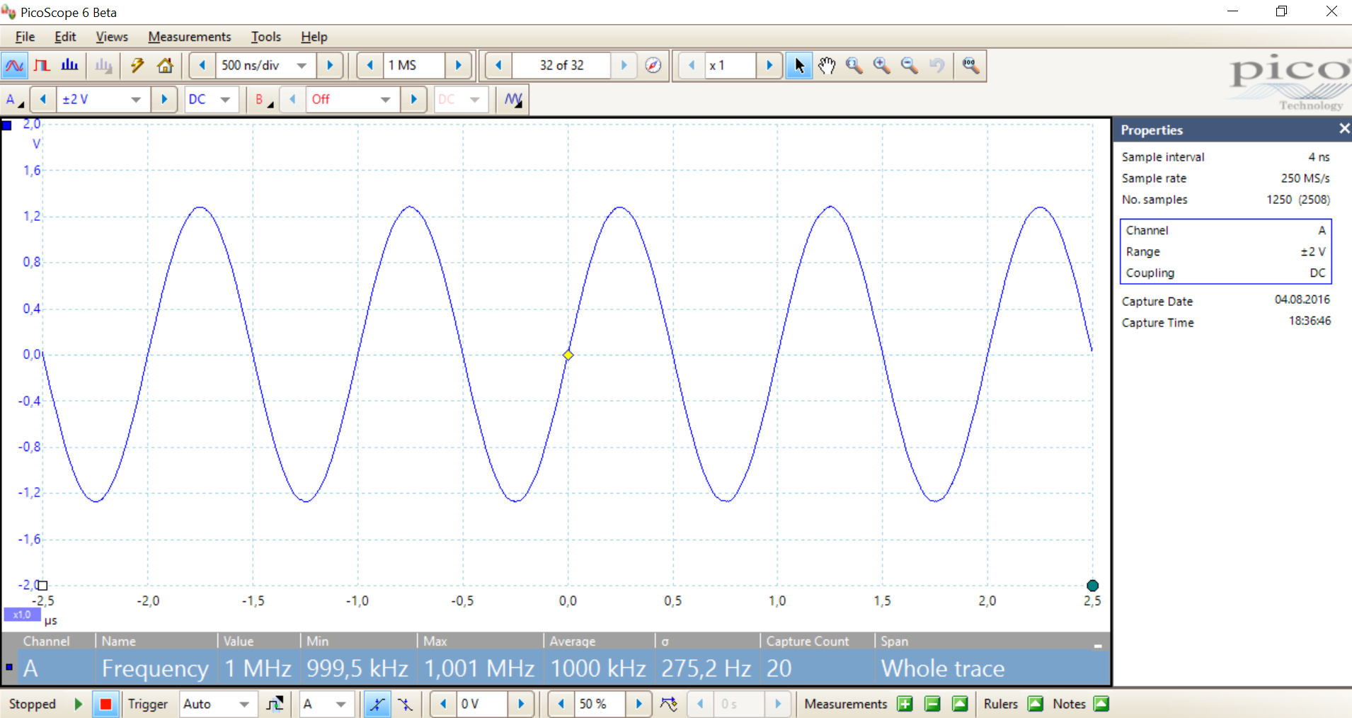
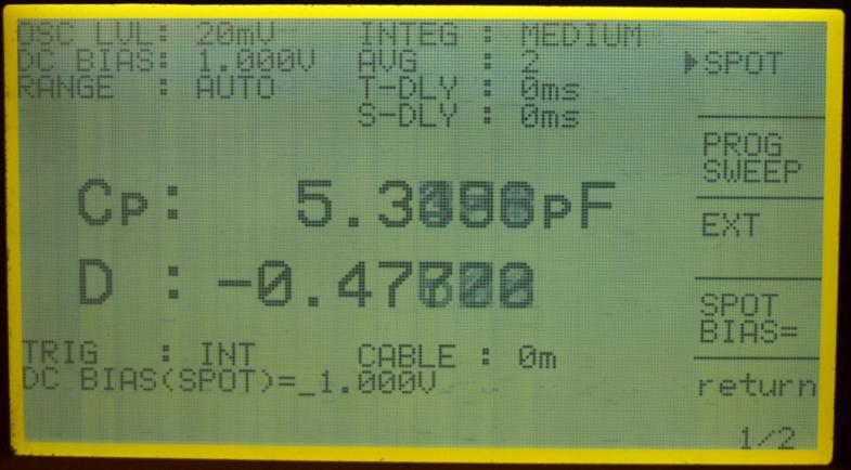
enlarge
shows the oscillator amplitude, here adjusted to the highest possible amplitude
Self Made Measurement Fixtures
| If you have enough time, make your own individual fixture for different measurement purposes. For testing small SMD parts it is better to buy a fixture made for that purpose. Cables custom-made is not difficult, manual describes how to fix two-wire and four-wire measurements. |
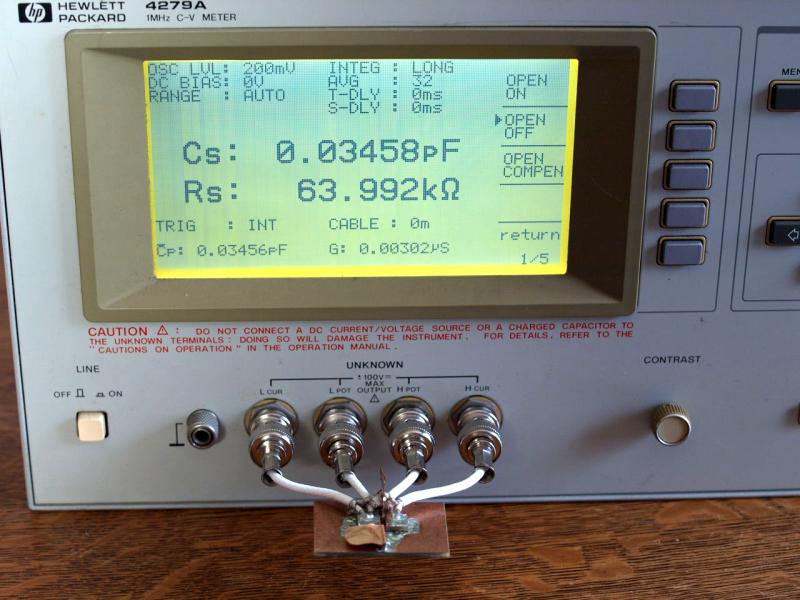
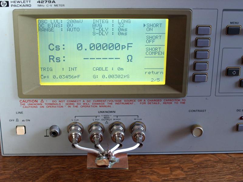
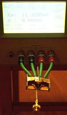
| Four
short BNC cables connceted in four-wire, soldered on a 50 ohm BNC
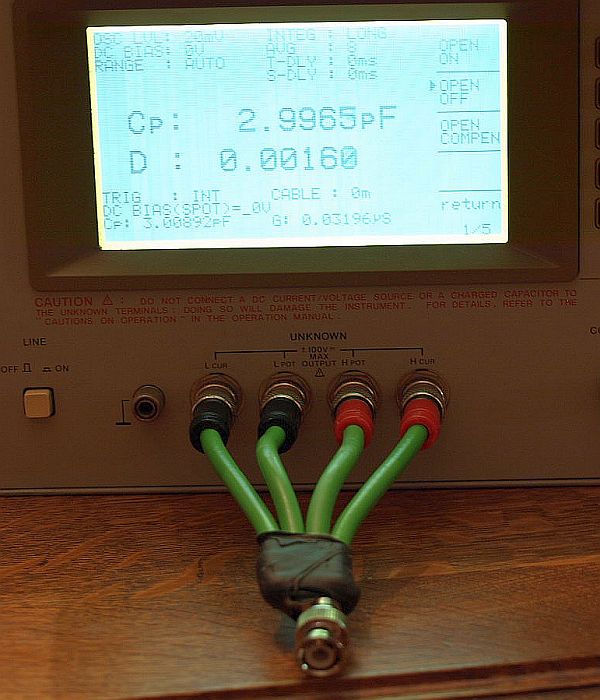
connector. Measures a 3pF capacitance of the BNC connector. With the OPEN ON, OPEN COMPON meter function this 3pF can be nulled to zero pF. The SHORT ON function null the ESR. Instrument has some more compensation functions, refer to manual. It is a way to measure capacitance of BNC-cables, adapters, connectores...... and devices with BNC inputs. |
|
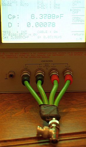
Left photo: Type A BNC-T-Adapter, Capacitance @1MHz: 6.3799pF - 2.9965pF = 3.38pF
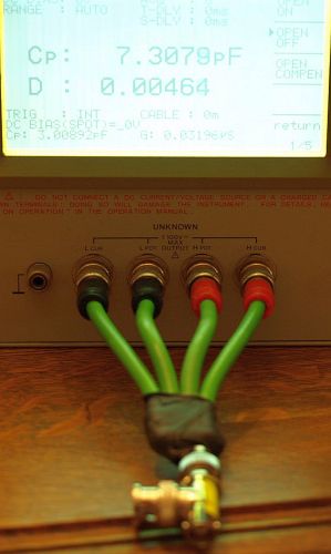
Right photo: Type B BNC-T-Adapter, Capacitance @1MHz: 7.3079pF - 2.9965pF = 4.31pF Type A was a higher quality adapter, Type B was a cheap adapter less than 2€.
|
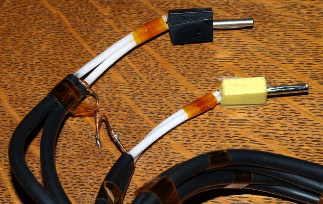
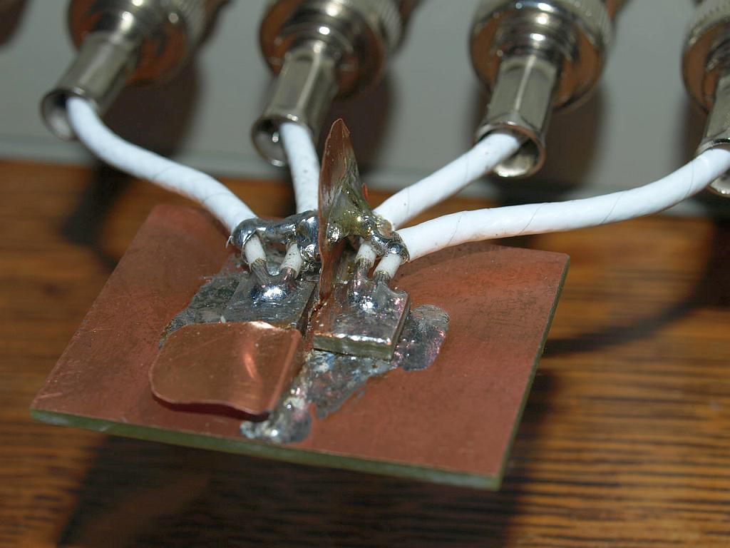
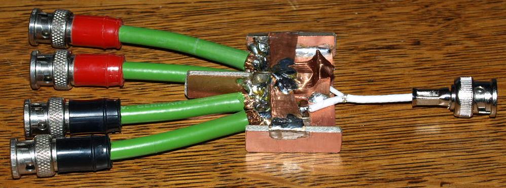
| Self
made cable with 4mm banana plugs. Measurement is guarded up to the
point where the four shields are connected. The instrument has three settings:
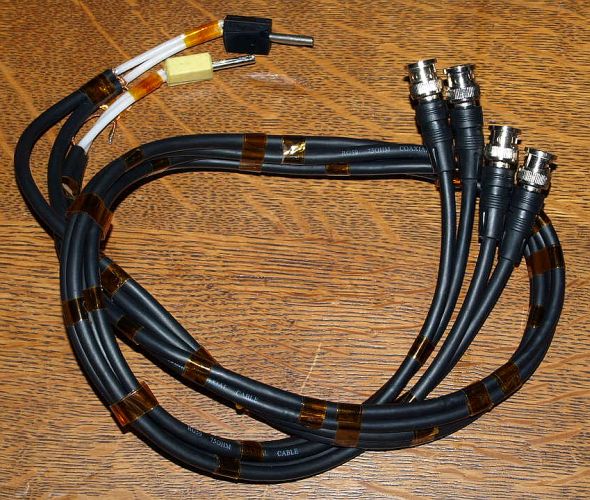
Open Components measurement was approx. 1.5pF, depending on distance between plugs. With the other green BNC-Fixture it was possible to trim each leg of the cable to the same cable capacitance. Each RG59 cable has 45pF. This RG59 (75 ohm) cable was unused since many years, I didn't know what to do with it, sometimes I cut them and use it for a shielded DC power supply. Many years ago, I bought ten of them new for less money - but less quality mechanical and electrical. Not a good choice for this measurement purpose, it has a stiff signal wire and will break after intensive use. Purpose ok for getting experience in building-up selfmades. |
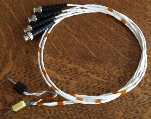
| Another 1 meter four-wire coaxial fixture, flexible to use. Reliable Teflon insulator. One cable has 223pF, two wires inside shield, paralleled. |
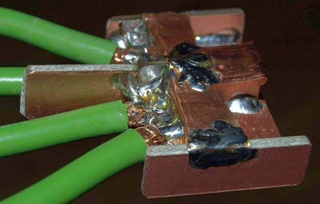
Custom-made fixture for measuring less pF
 |
 |
 |
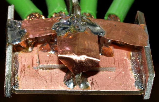
| Fixture with only 35 femto Farad parasitic capacitance. | Compensated to zero using OPEN and SHORT Compensation function. | Guard-Ground connected close as possible to the DUT. Changeable guarded shield between measurement plates. Bottom guarded shield reducing stray capacitance to earth ground. |
|
Building your own fixture is a helpful way to understand and learning the measurement.
Unfortunately I don`t own any original fixture and no original 1m and 2m cables, they are seldom available on the second hand market. Finding an instrument together with some original fixtures on second hand is almost impossible, fixtures and accessories getting lost in most cases. With this fixture small capacitors can be soldered on the plates or pressed on the plates by a small piece of wood. This construction is a good starting point for building-up an SMD measurement fixture holding parts via springs or screws. A professional solution is a question of combining precision mechanic with understanding the parasitics. For understanding the parasitic: "draw in your mind the electric field between the both plates". For example here the field between is small, the plates standing not parallel to each other. The remaining small field between the plates is guarded with a shield, also the bottom shield reduce approx. 50% of the stray field between plates and reduces the direct stray field to earth ground. Prevent stray fields to earth ground. Connecting the coaxial-shield close to the DUT at one point reduce spreading currents within the copper shield. A shield carrying less currents creates a lower parasitic magnetic field. Soldering the POT+/- terminals close to the DUT, results in best ESR,D,Q measurement. Soldering the CUR+/- terminals close to DUT reduce spreading current within the plates. The POT+/- can be closer to DUT than the CUR+/-. POT terminals measures and CUR terminal drives current. Of course there are many ways to improve this shown fixture, this was only an example.
|
Atto Farad Fixture
| Building
up another fixture with only 660 Atto Farad parasitic capacitance. The
two plates are still accessable for soldering wires. Unit not yet cleaned from solder flux. (The cable is a redesign from the first fixture described above, the BNC connector was soldered blank on the hot-wires, breaked, was mechanical not stable). |
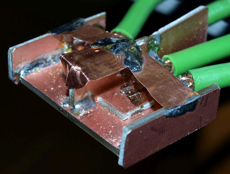
| Plates well
shielded and still accessable. When building up such a construction
every single soldered step was tested for its improvement. The remaining stray field from one plate to the other must travel a long way. Most parasitic ways are shielded through the measurement guard, there is no direct "short circuit" for the field. It´s always a good method to keep in your mind "how the electric field will spread". With this knowledge it is possible to make a good custom-made fixture for many measurement tasks. There is no fixture which is suitable for all measurements, each task has its own mechanical demands, e.g. wires, needles or SMD parts. After understanding how the field is spreading a good custom-made fixture is a question reduced to the mechanical design. When doing such experiments the positive side-effects, knowledge about "behaviour of electric stray fields", useful for other tasks like Layout and EMC considerations in critical designs. With such a C-V meter it is also possible to find difficulties on existing PCB´s, but such a measurement requires the build of a special custom-made fixture. |
| BNC
DUT connector with a small piece of a Teflon coaxial cable. This cable
type is not a HF cable, I guess it is made for shielded low frequency
applications. The hot wire is flexible, thick and very near to the
coax-shield. Hot-wire insulator is made of solid massive teflon,
resulting in a higher capacitance. The cable is very reliable and
mechanical strong for difficult environmental conditions. Soldering a wired DUT on this fixture, simple and fast.
DUT shows 11pF, approx. 3pF caused by the BNC connector, cable has many pF/cm.
|
| A C-V
meter is a useful instrument in each labority and can takes away the
"fear from handling and understanding small capacitances". There are not so many pF-Range instruments available with high resolution, combined with the wide adjustable DC-Bias and the fast measurement rate. Main use was semiconductor industry and part manufactoring. But also useful for many purposes like circuit development and PCB issues. I wished I could have a modern type of actual sale. It is really a pleasure to explore and work with C-V meters. |

HP Gallery Main Gallery Impressum