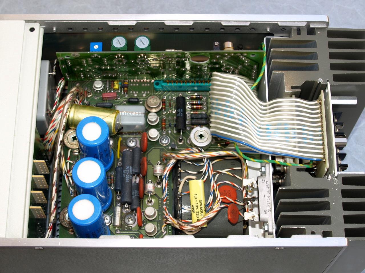
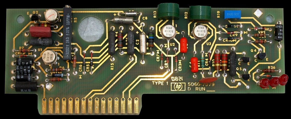
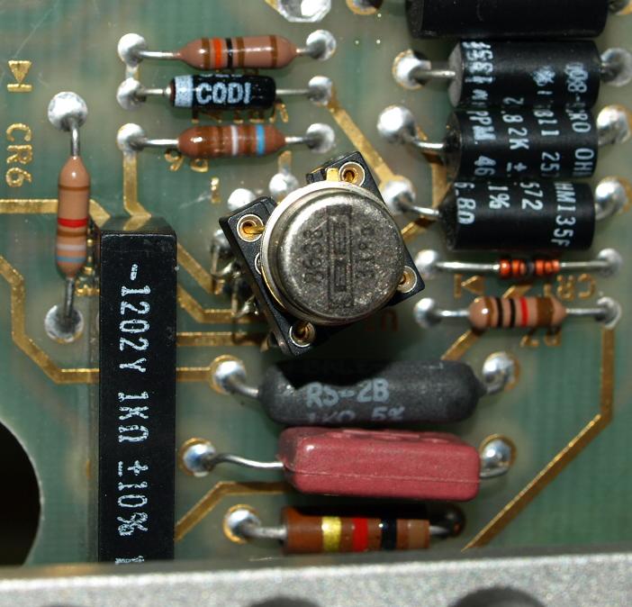
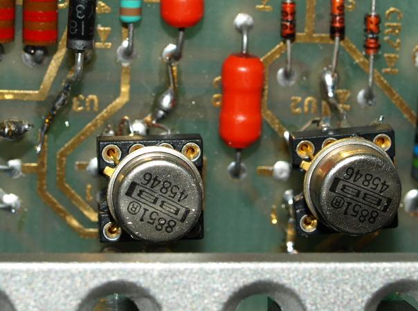
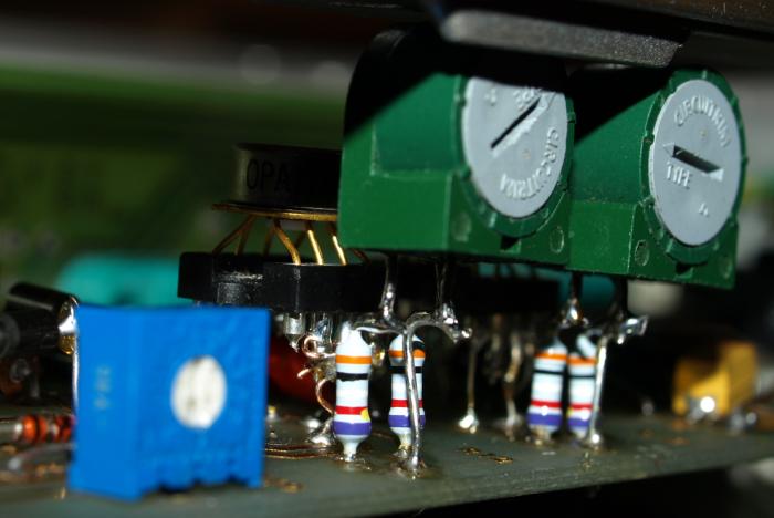
Changing operational amplifiers can
be a terrible task getting the control loop stable again. First I tried
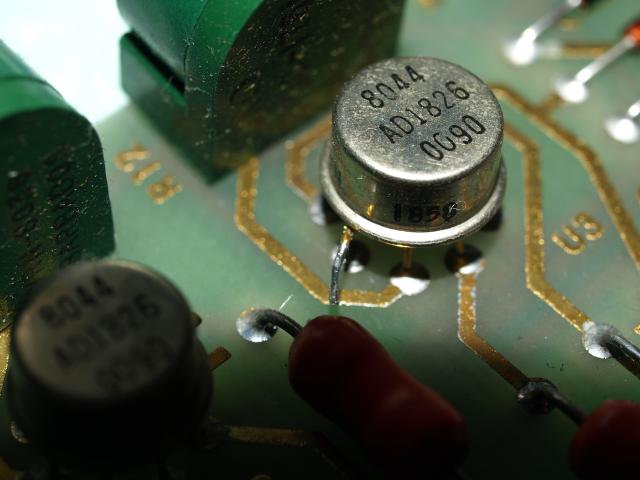
some DIL-8 types, later I choosed some good performance TO-5 types.
Their pinout and offset trimming pinout was similar to the old 741
family. All three control loops are stable over load, time and
temperature, these are three things you must observe. The used Difet
has much lower input bias currents and noise, higher open loop gain and
less offset voltage and drift and the speed is higher, but be careful
with high speed types some tend to oscillate. - choosed type is well
suitable for integrator functions. I won't recommend the type, try
yourself there are many available types on the market. But don't make a
hype by changing op amps, the circuit worked also nicely with the
old 741 family.
Calibration Procedure
This chapter shows how to calibrate the instrument.
For a accurate calibration please read the manufactorer manual.
The description here follows close to the instruction manual - but not in all items.
Always observe all jumpers on the
photos - I can't a warranty that I not forget onetimes to mention when
jumoers shall be removed or replaced again.
The photos are correct, the text max be not. I repeat it again, use the original manual for a valid calibration.
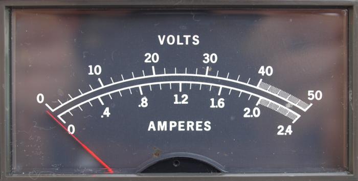
1. Mechanical Meter Zero
Turn OFF instrument, insert a sharp pointed object in the black slider
and move pointer position clockwise until the pointer will reach zero
point.
Move pointer slightly counterclockwise to free the pointer from suspension.
2. Gross Current Limit Adjustment
Use a
33 ohma load at
40VDC output under lowest AC-line voltage
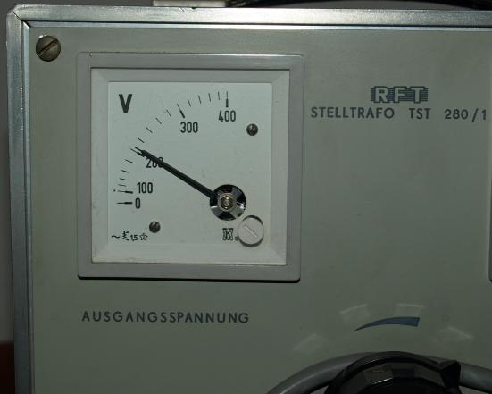
An AC variac is a recommended source for repair and calibration.
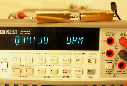
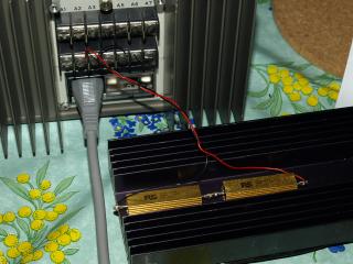
34 ohm load resistor
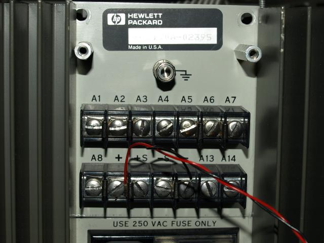
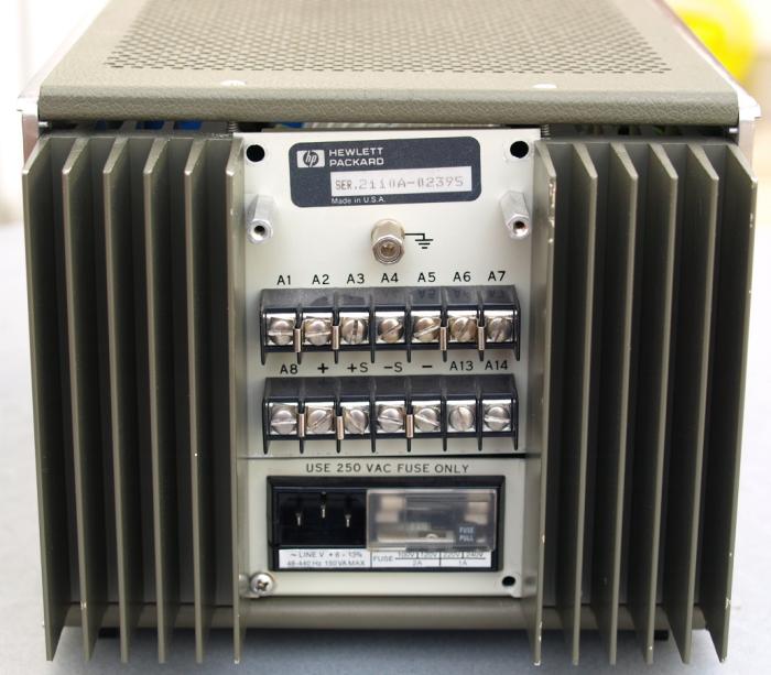
Connect load on the rear output. The rear output is sensed., the front output not.
Instrument has many programming possibilties in current and voltage
through external analog settings, difficult to describe in detail, read
manual.
Keep the load cool - 47 watts applied power.
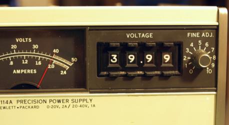
Set output voltage to
40V
Adjust cross current limit on the trimmer in the middle
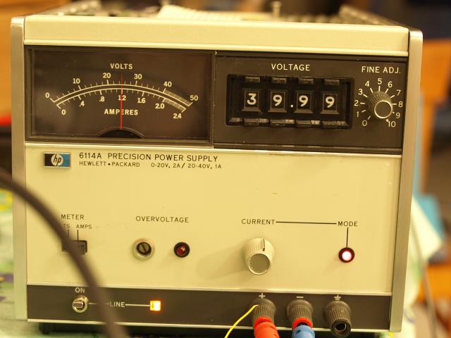
Set Front Panel Meter to
AMPS position.
Turn CURRENT control full clockwise, adjust trimmer so that current mode LED just starts lights at
60% of maximum rated current.
I removed the load after adjustment.
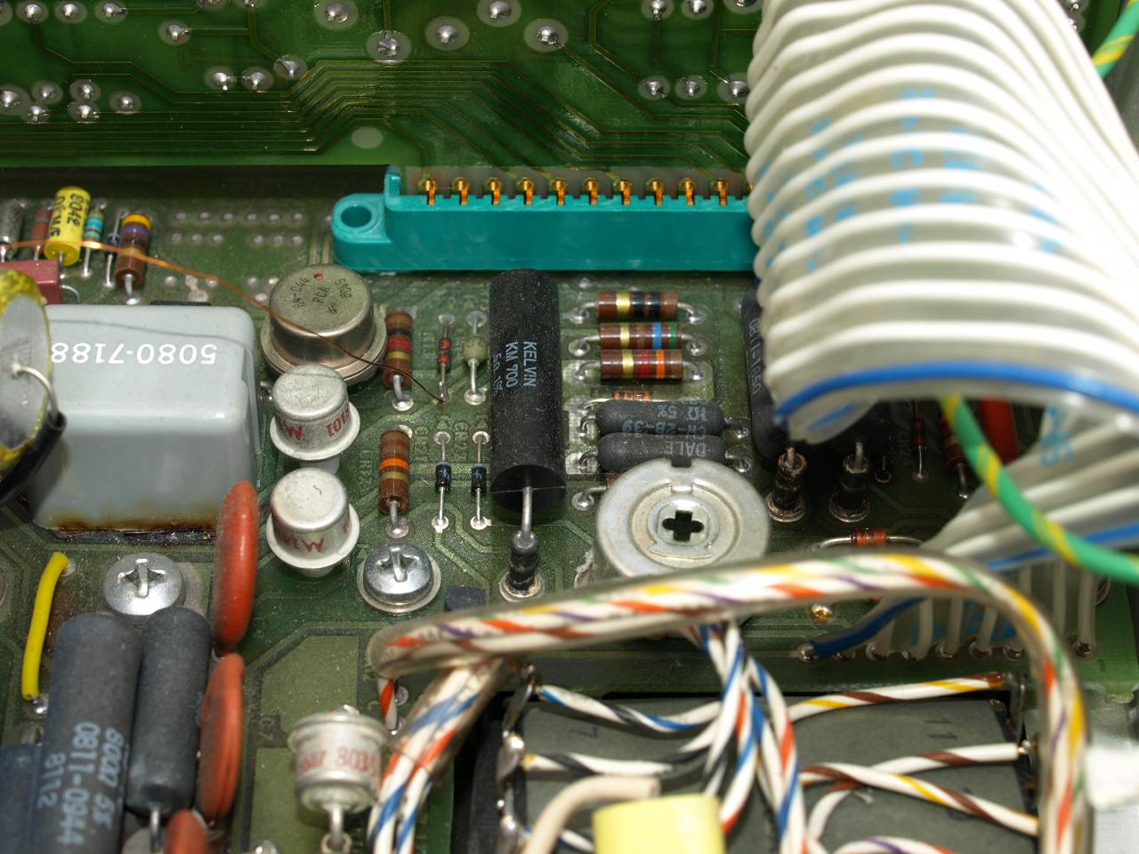
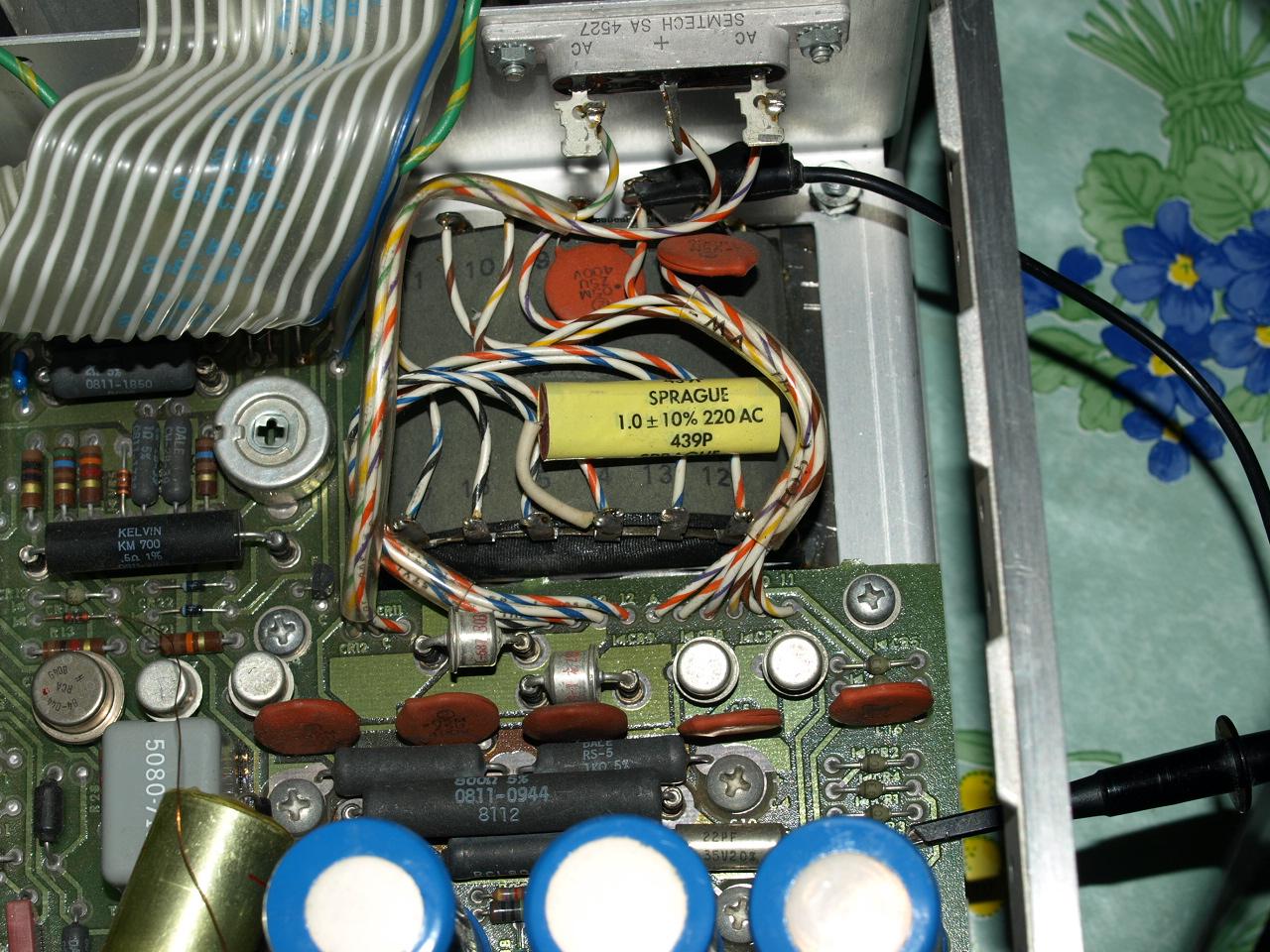
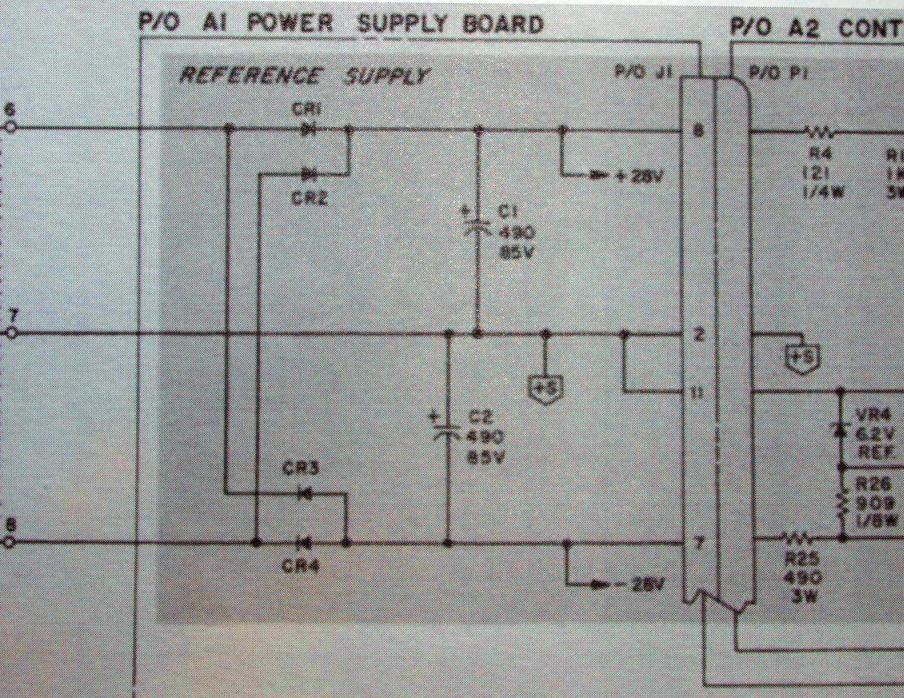
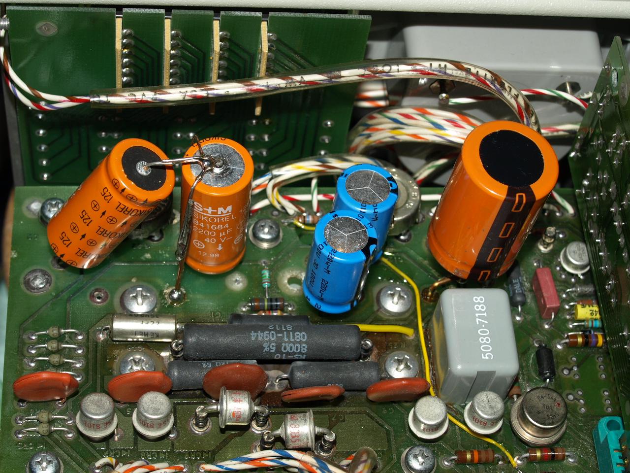
3. Reference Supply
Warm-up a DMM with a high accuracy. Warm-up the power supply for at least 30 minutes.
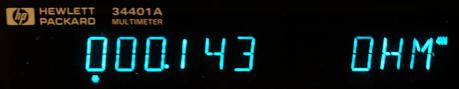
Measure voltage on the temperature compensated zener voltage reference against + output.

The meter should read a voltage greater than
6V. If not read the instruction in the manual what to do.
With 6.3V here the zener current is large enough that the 1N829 will operate with a recommended operating current range.
If the diode operates under too low currents, important parameter worsen:
- temperature coefficient
- dynamic resistance
- noise
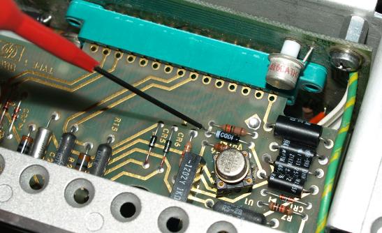
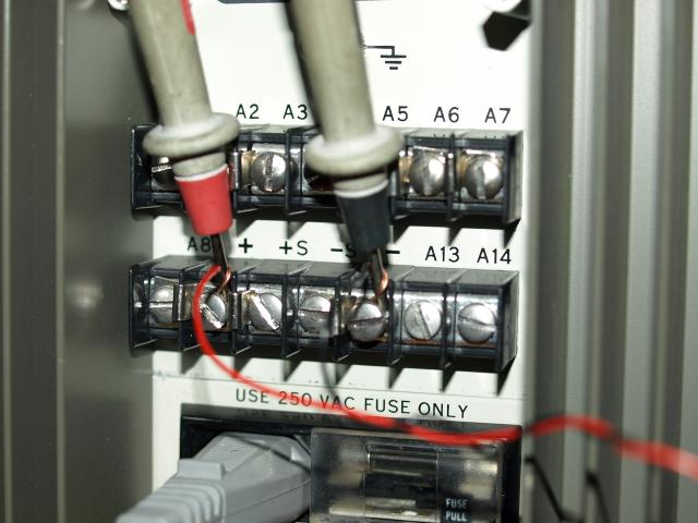
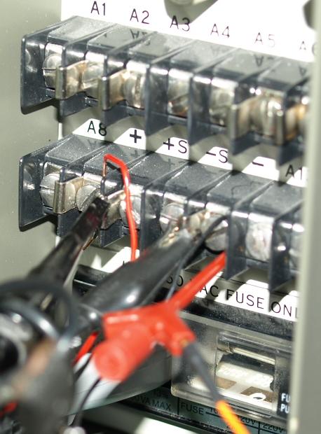
4. Zero Output Voltage
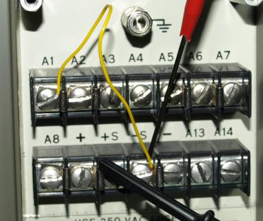
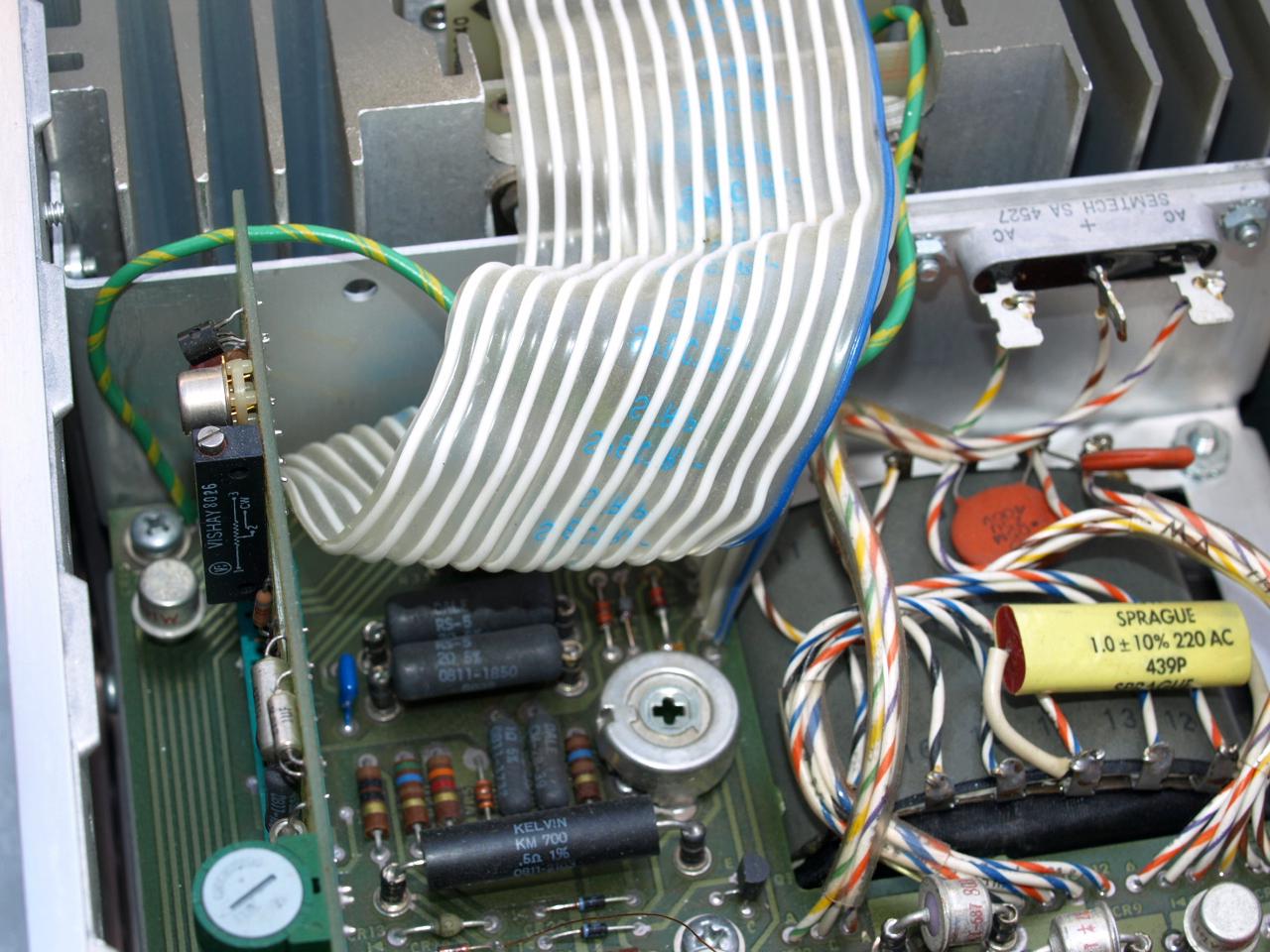
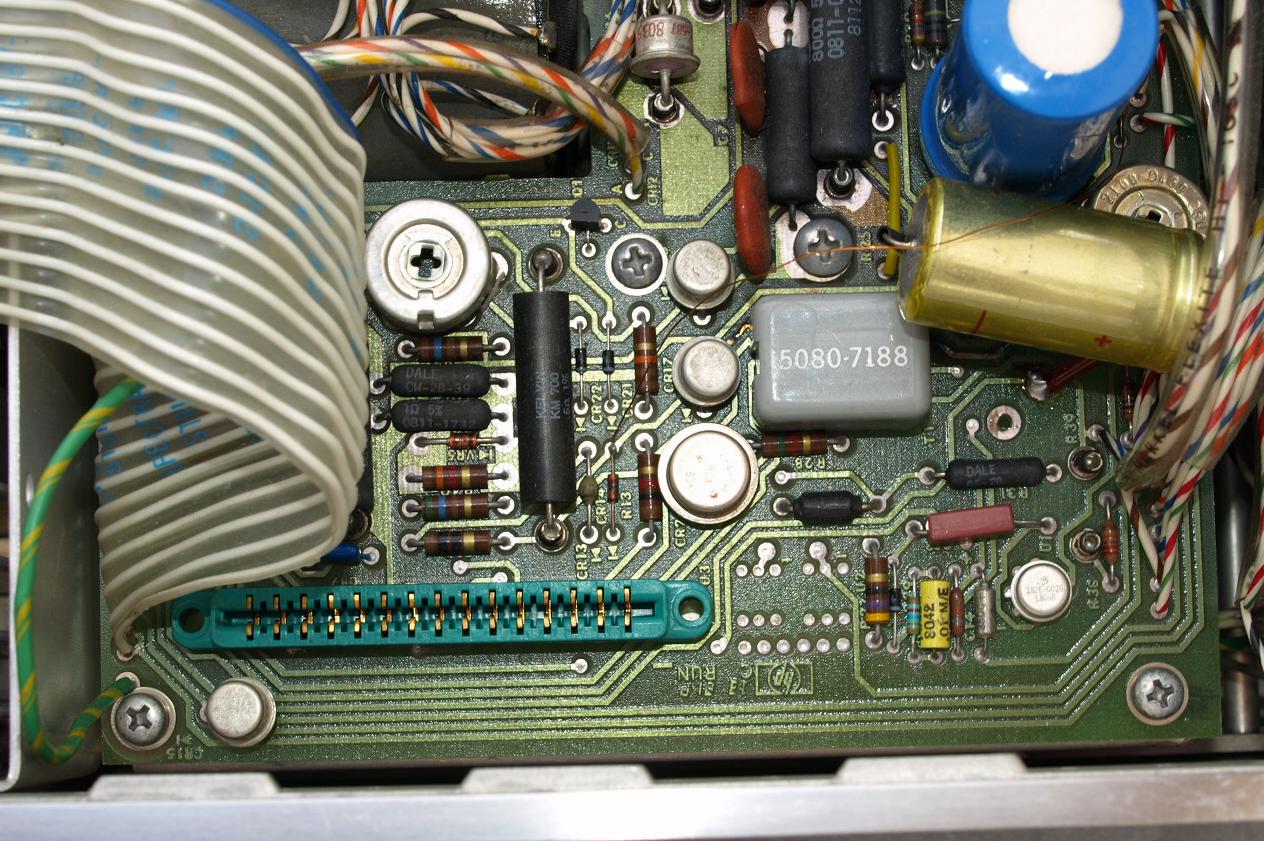
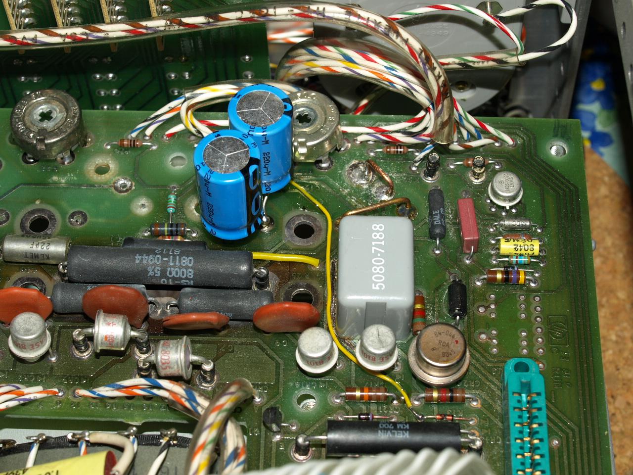
Short out the voltage control loop by a short-circuit (yellow wire)
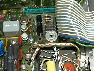
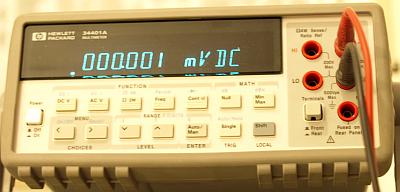
Adjust trimmer (green) R13 on board A2 for a
-450+/-50µV between +S and -S.
(Note: I adjusted the voltage to exactly zero voltage not to the recommended value in the manual).
This trimmer sets the opamp offset voltage of the voltage control loop to zero (with my adjustment).
Zero voltage values differing, depending if measured on rear or front terminals - I choosed the rear terminals.
I hope your are satisfied.
Observe for some minutes for a stable voltage, low frequency oscillations and offset drift can be detected.
In this measurement the yellow wire applies a zero voltage to the noninverting input of the voltage loop operational amplifier.
The +output applies on the inverting op input, when both voltages are
equal the loop is in regulation. The trimmer sets the operational
amplifer offset voltage to zero.
5. Voltage Programming Current
Turn power supply OFF.
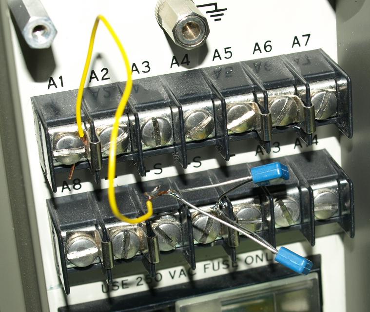
Connect the yellow wire as shown.
Remove jumper between A2 and A3
One side of the yellow wire is connected to a high precision 1 kohm series resistor conncted to -S.
(here a two paralleled 2k used).
Apply the high input impedance DMM across the resistor.
Turn ON supply.
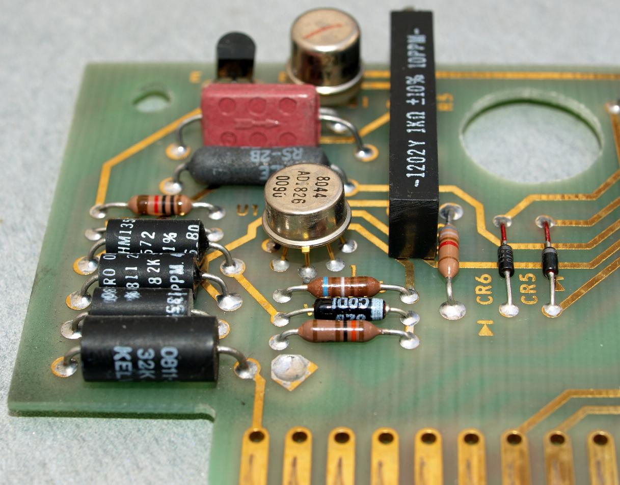
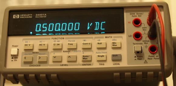
Adjust A2 R5 (long black trimmer near 1N829) for a reading of
0.5V +/-5µV
Turn OFF supply
Replace A2 to A3 jumper.
I hope your are satisfied.
This adjustment set the current flowing through the digital output voltage setting resistors.
If this voltage is not stable, then there are problems in the +16V
reference voltage loop. Observe this value for stability, all
output voltages depending on this voltage.
This measurement sets the scale factor of the output voltage control
loop. This constant voltage drives a constant current through the
digital selectable gain setting resistors.
Resulting voltage across gain setting resistors program the voltage control loop.
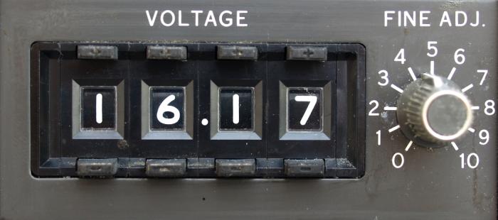
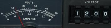
6. Voltmeter Calibration
Adjust A1 R22 (right trimmer near the front panel in the right corner) for a corret front panel voltmeter reading.
7. Zero Output Current
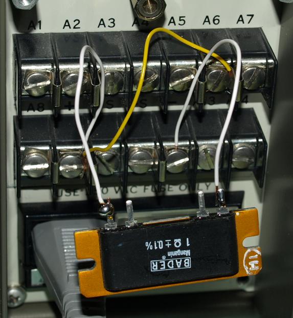
Turn supply ON.
Program output for 2 volts.
Place the yellow wire.
Connect a 1 ohm resistor and measure voltage across resistor.
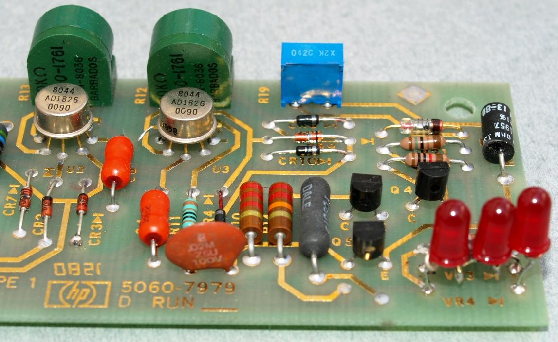
Adjust A2 R12 (green trimmer) to
0V+/-10µV on DMM
Turn supply OFF.
Remove yellow wire.
Don't use that long lead wires like shown, causing error.
Current control loop set to a zero output current. Trimmer R12 (U3 opamp offset contro)l sets the current in the load to zero.

I hope your are satisfied.
Zero Current = 0.003mV/1ohm = 3µA
Observe this value for stability within some minutes.
8. Current Programming Current
This adjustment will set the programming constant current flowing through the CURRENT MODE potentiometer.
A diode-transistor current mirror generates a 1mA current.
The CURRENT MODE potentiomer has a nominal 1k resistance, with a
1mA current 1 volt drops - and this voltage set the current loop on the
noninverting opamp input.
The internal output current sensing resistor has 500mOhm and applies on the inverting opamp input.
With 2A output current:
2A*500ohm=1 volt
1mA*1kohm=1 volt
When both voltages are equal the current control loop is in regulation.
This adjustment ensures that a maximum set clockwise CURRENT MODE 1k
potentiomer will set exactly the output current limit to 2A.
For example when using a 1k 10-turn potentiometer the current limit could be easily calibrated to 200mA/360°.
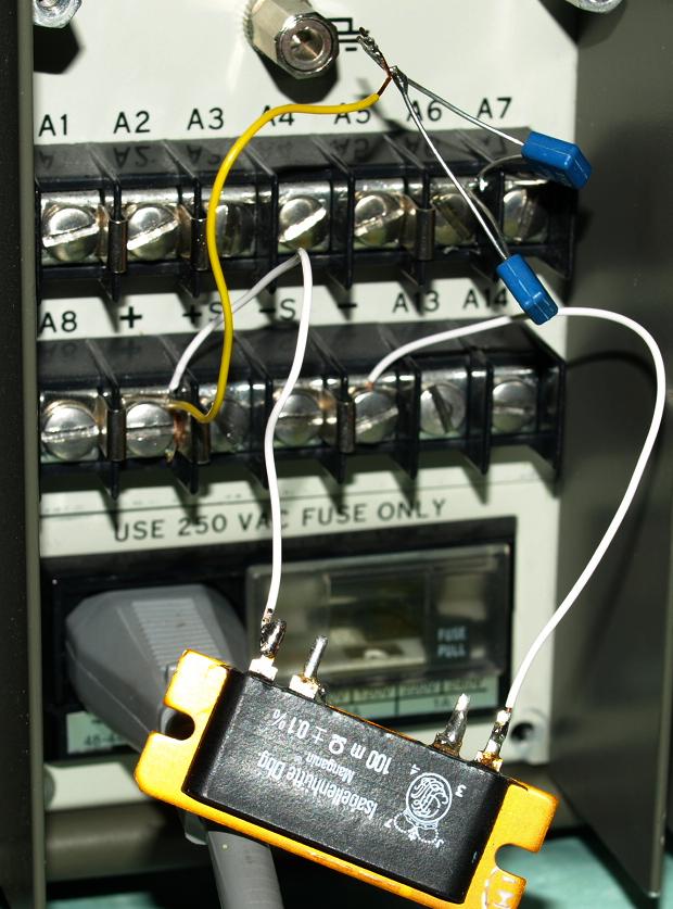
Such a calibration don't work - 100 mOhm resistor with long thin wires.
Turn OFF supply
Remove jumper between A6 and A7.
Connect 100 mOhm across output.
Connect a precision 1k resistor A6 and + output
DMM on output voltage
Program for 2 volts and turn ON
Adjust A2 R19 (blue trimmer) for a reading
-0.2V+/-250µV
Resistor in 4W measurement at the end of the white wires , a bad
configuration, the -0.2V can not be reached. This method works only
with precise 0.1 ohm between + output and -output.
I choosed another method:
Measure the voltage drop across the 1k precision resistor, if A2 R19
exactly adjusts a 1V drop, the current limit will reach 2A with a 1k
potentiometer in maximum clockwise position.
This was a good example:
If you calibrate something - always think about what you are doing - try to understand the circuit first.
9. Ammeter Calibration
Adjust A1 R17 (trimmer closest to front panel meter) for a correct reading, compare and measure the load current with a DMM.
Accuracy Measurements
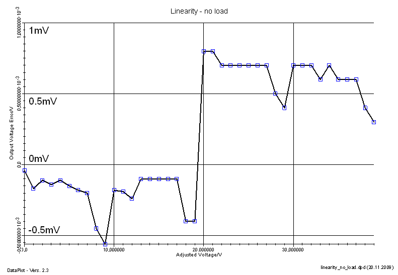
Linearity without load
Power Supply and DMM (34401A) warm-up for 1 hour.
This plot shows the Output Voltage Error vs. Adjusted Voltage
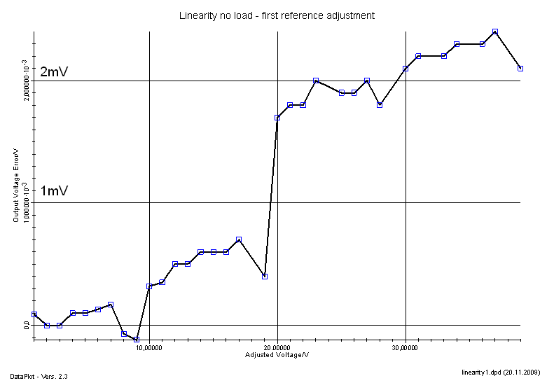
This plot shows the Output Voltage Error vs. Adjusted Voltage with a
slightly readjusted internal reference voltage trimmer R5 on board A2
The maximum error reaches:
+800µV for a 20 volts output.
-600µV for a 9 volts output.
This is an accuracy within:
+0.004% (+40ppm)
and
-0.006% (-60ppm)
This power supply reaches almost absolute 16 bit accuracy.
1LSB=40V/65536=610µV
After repeating it would be a good idea trying to fine trim the digital resistor devider with parallel or series resistors.
A trimming could remove the large jump between 19V and 20V and an absolute 16 bit performance could be reached.
This was a time demanding measurement applying 1 volt steps and writing down the results.
Linearity with a 34 ohm load
The load will cause maximum 1.2A and 48 watts power
.
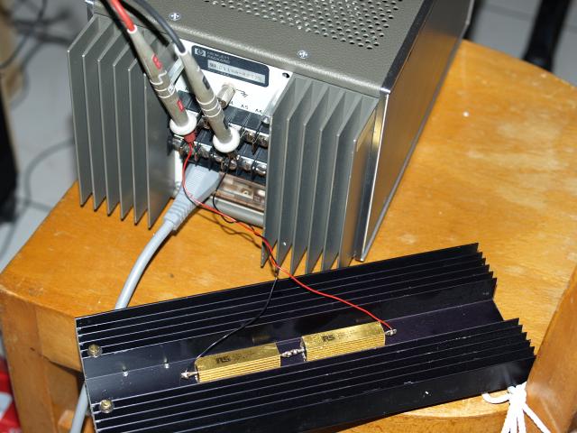
34 ohm load on a heatsink
This is not a good sense and load connection, the wires are under the srcews.
Power Supply and DMM (34401A) warm-up for 2 hours.
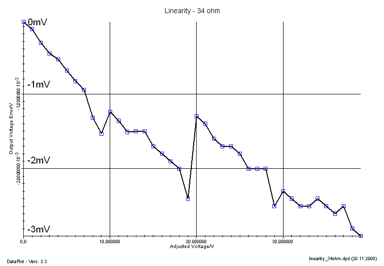
The voltage drop in the terminals with rising current.
Manufactorer specifies a 50µOhm output resistance, under a 1.2A
current cause this a voltage drop of only 60µV. The bad
connection is the reason for the large error.
Dynamic Measurements
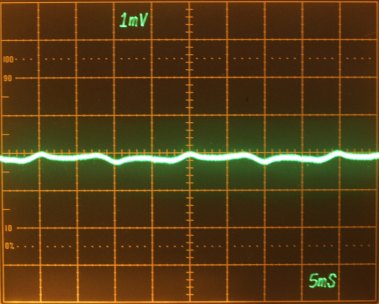
Output noise with and without load
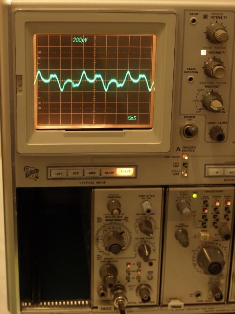
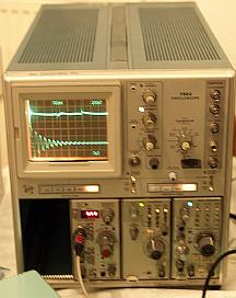
Using a
7A22 set to a 10Hz - 1MHz bandpass
Oscilloscope powered with the AC variac, 6114A on AC-line
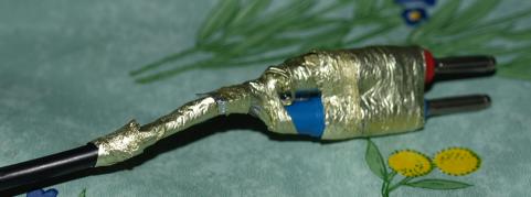
Using shielded cables. These kind of maesurement are difficult, you
never know if measure real signals or parasitic ground loop signals.
Try different grounding schemes, I haven't tried other ground and shielding configrations here.
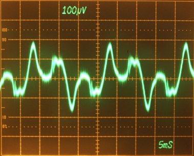
No load
(Oscillogram looks similar to any output voltage).
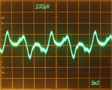
34 ohms load at 10 volts
(Unexpected, ripple had become lower with load).
Changing to a
7A13 Amplifier Plug-In,.
Under use the internal adjustable DC voltage on the inverting input.
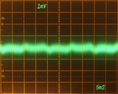
34 ohms load at 10 volts.
7A13 set to bandwidth DC to appr. 100 MHz (full range)
34 ohms load at 10 volts.
7A13 set to bandwidth DC to 5 MHz.
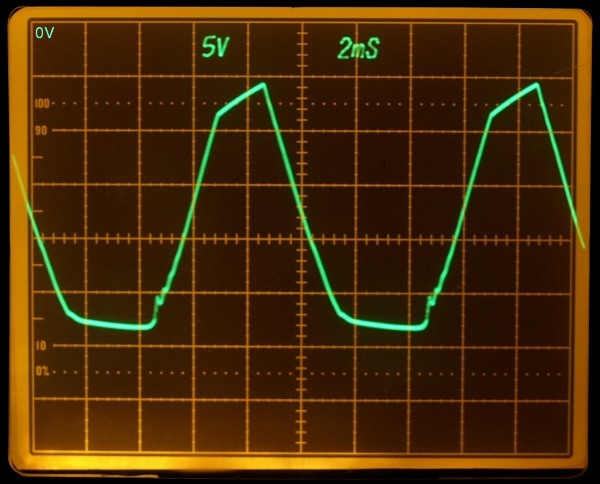
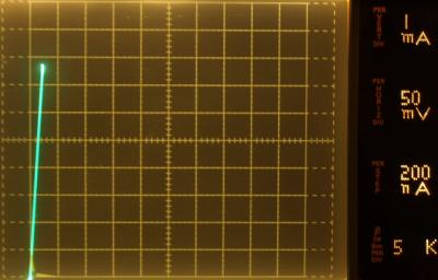
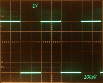
Output with a switched load
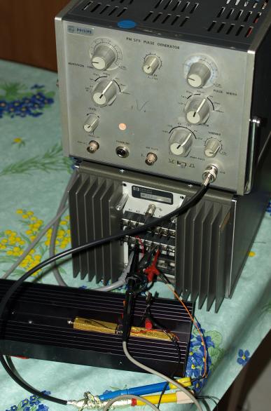
34 ohms load switched by a small MOSFET controled by a pulse generator.
Output voltage probe measured directly on the sensed outputs.
output set for 12 volts
Using a 7A13 in AC position up to full bandwith and a second intensified timebase.
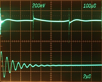
Upper Trace AC coupled power supply output, 100µs/Div.
Lower Trace zoom of intensified zone, 2µs/Div.
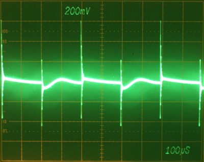
The inductance of the load wire-wounded load resistance, the wires
togehter with capacitances from the MOSFET and the output creat a
LC tank oscillating at approximately 800kHz resonance frequency.
The power supply contol can't reject this higher frequency contents,
this is an excepted result due to the integrating precision
control loop character.
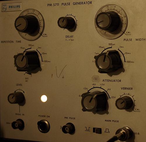
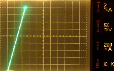
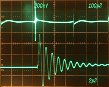
Set the puls generator
Gate Source Voltage
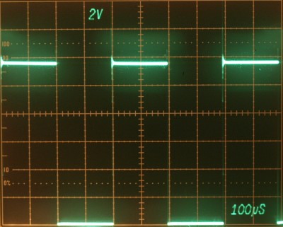
Drain Source Voltage
With this parasitic-LC load (34 ohms) appearing very high switching transients of more than 5 volts.
Power Supply Output voltage
Control loop rejects this higher frequency contents from 5 volts to approximately 600mV.
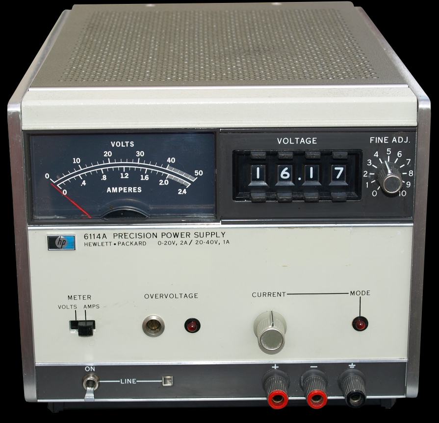
Conclusion
I like this fine power supply, handy size, current control,
overvoltage protection, high accuracy and less ripple make it a useful
instrument for the labor.
It was much work to repair all the faults.
When I remember repairing this instrument costs me about 30 hours of
hard working, including the time for understanding circuit and
calibration, not counting the hours of writing this note.