7D12 AD Converter with M1, M2 and M3 |
|
|
|
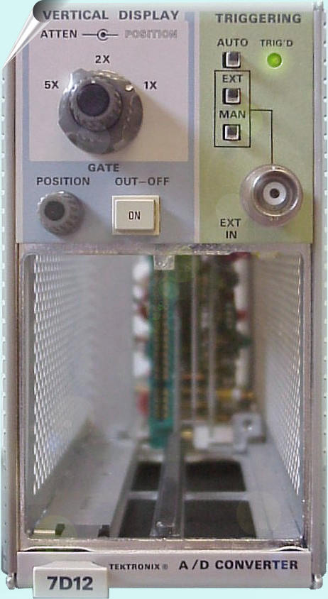
Der 7D12 ist ein analoger zu digital Konverterfür den Gebrauch mit jedem möglichem 7000er Oszillograph mit Readoutfunktion. Es gibt einige Einschübe für den Gebrauch mit dem 7D12. Abhängig vom Einschub sind bis zu 4 1/2 Stellen anzeigbar mit einem Messwert von 20000 auf der Kathodenstrahlröhre. Wenn sie nicht benutzt wird, ist die höchstwertigste Ziffer der Anzeige unterdrückt. Automatische Polarität und Überlaufanzeigen sind auch im 7D12 eingebaut. Der AD Konverter kann durch das Einsteckmodul, manuell durch einen Schalter oder von außen von einer Triggerquelle wie dem Periode 7D15 Timer intern ausgelöst werden. Der 7D12 enthält auch einen vertikalen Verstärker, der das Signal anzeigt, das am Modul anliegt, und einen Verstärker, der eine Darstellung des internen Signals des Gates vom 7D12 anzeigt. Da die Funktion des 7D12 durch das angebrachte Modul festgesetzt wird, sind die Anweisungen für den Betrieb des 7D12 in der Bedienungsanleitung für jedes Modul (d.h., M1, M2 oder M3) nachzulesen. The 7D12 is an analog to digital converterfor use with any 7000 series oscilloscope mainframe that contains readout. There are some mini plug-in available for use with the 7D12. Depending on plug-in the 7D12 can supply up to a 4 1/2 digit display with a full scale reading of 20000 on the mainframe cathode ray tube. When not used, the most significant digit of the display is suppressed. Automatic polarity and overflow indicators are also contained in the 7D12. The AD Converter can be triggered internally by the plug-in module, manually by a front-panel switch or externally from a trigger source such as the 7D15 Period Timer. The 7D12 also contains a vertical display amplifier that displays the signal applied to the module, and a gate display amplifier that displays a representation of the 7D12 internal gate signal. Since the 7D12 function is dictated by the module installed, instructions for operating the 7D12 are located in the Operating Instruction for each module (i.e., M1, M2 or M3). |
|
|
|
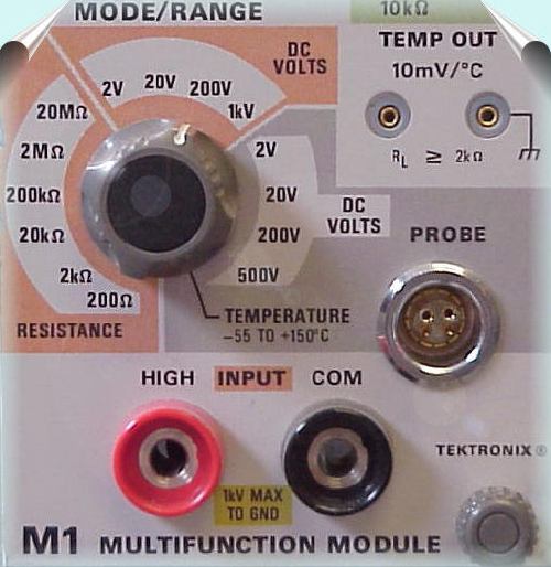
The M1 Multifunction Modulecan be installed in the 7D12 plug-in. The M1 is capable of measuring resistance, DC volts, and temperature. The floating INPUT allows up to 1000 volts elevation from ground, with a 10 megohm input impedance on the DC scale. The input to the M1 is presented as a digital readout on the cathode ray tube of the associated oscilloscope, along with information encoded by other plug-in units. |
Multifunktionsmodul M1Das M1 ist geegnet zum Messen von Widerständen, Gleichspannungen und Temperaturen.. Der floatende Eingang kann bis zu 1000 Volt Common Mode über Masse, bei einem 10 Megaohm Eingangswiderstand im DC Bereich. Der Eingang des M1 ist dargestellt als digitale Anzeige in der Kathodenstrahlröhre zusammen mit anderen Informationen über die Messung. |
|
|
|
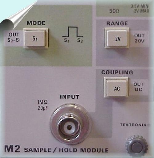
M2 Sample and Hold ModuleThe M2 Module is designed to measure the voltage amplitude or the difference voltage between any two points of a waveform connected to the INPUT connector. Two separate analog displays are presented on the mainframe CRT; the signal waveform to be measured that is connected to the 7D12 EXT IN connector. The point of measurement on the waveform coincides with the trigger signal transition point. The input to the M2 is presented as a digital readout within the upper division of the cathode ray tube viewing area, and the vertical sensitivity is presented directly below in the lower division of the CRT viewing area. A Tektronix P6055 probe, which is equipped with a readout coding ring, can be used with the M2 Module to extend its range. The readout coding ring on the probe connects the readout displayed on the CRT to the actual deflection factor at the probe tip. |
M2 Sample und Hold EinschubDas M2 Module wurde gebaut, um die Amplitude oder eine Differenzspannung zu messen, die zwischen zwei Punkten einer Kurvenform auftritt. Diese Waveform ist am Eingang angeschlossen worden. Das Modul blendet zwei digitale Anzeigen in der CRT ein. Das Signal ist angeschlossen am INT Eingang. Der Messpunkt kann einstellbar getriggert werden. Die beiden Anzeigen erscheinen oben und unten in der CRT eingeblendet. Ein Tektronix P6055 Tastkopf kann zusammen mit dem M2 Modul verwendet werden. Der P6055 Tastkopf kann den Meßbereich erweitern und dies wird auch in der CRT angezeigt. |
|
|
|
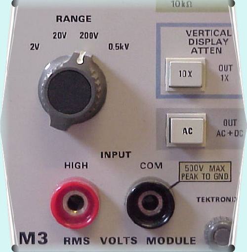
M3 RMS Volts ModuleThe M3 Module converts the input signal to a DC equivalent of the true RMS value of that signal, in either AC or DC coupling. The input signal is displayed on the mainframe CRT, and the RMS readout is presented in the upper division of the CRT viewing area. The vertical sensitivity readout is presented directly below, in the lower division of the CRT viewing area. |
M3 Effektivwert Spannung Moduldas Modul M3 wandelt das Eingangssignal in ein DC Äquivalent des entsprechenden Effektivwert Wertes dieses Signals, die entweder AC oder DC gekoppelt sind. Das Eingangssignal wird auf der Mainframe CRT angezeigt, und der Effektivwert kann ausgelesen werden im oberen Sektor der CRT. Das Auslesen der vertikalen Empfindlichkeit geschieht unten im unteren Teil der CRT. |
|
|
|