|
|
Ultra Low Distortion Test Equipment Messgerät für sehr kleinen Klirrfaktor |
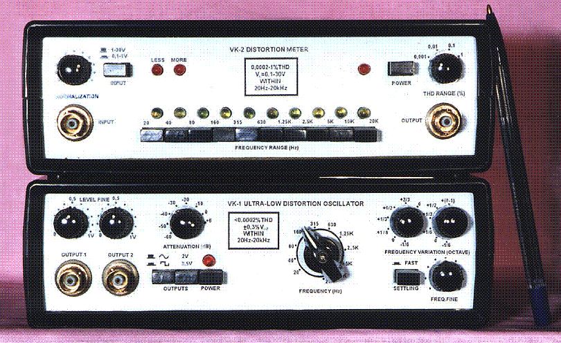
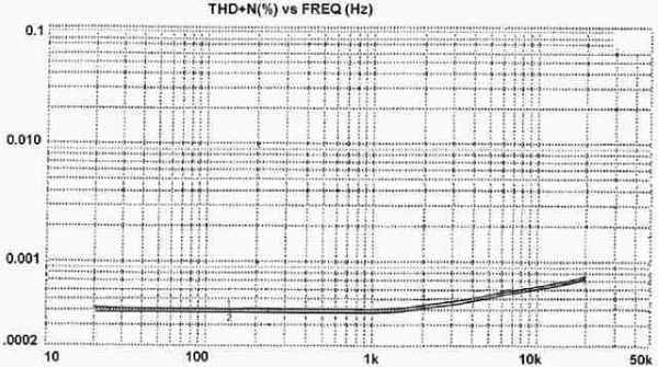
Orginaltext des Herstellers - original manufactorer description: Project VK-1 and VK-2 Ultra low Distortion MeterThe represented here is a project which best corresponds to the motto of this site www.amplifier.cd – audio free of distortion. It is based on two instruments, VK-1 audio oscillator and VK-2 distortion meter, that allow you to confidently evaluate in what degree your audio equipment is free of distortion.The measured figures of total harmonic distortion (THD) can be as low as 0,0002% within 20Hz-20kHz, but if this limit seems too high, just add an ordinary PC (with SpectraLab 4.32software installed) and you will observe on the monitor the separated harmonics of distortion down to –145dB. The oscillator and the meter are compact enough to put them into a brief-case and areconvenient and simple in use enough to become very popular among electronics amateurs and audio enthusiasts. For an experienced electronics designer, the availability of the VK-1, VK-2 combination is vital in achieving a real breakthrough in developments and I myself, having this set at hand, in very short terms have built the range of audio components with unprecedented characteristics (for example, a super-linear power amplifier with THD of less than 0,0008%at a 70W power into 4-Ohm load within 20Hz-20kHz). Manufacturers of precision electronic components can find these instruments very useful too, when testing their products. VK-1 oscillator and VK-2 distortion meter are unique not only by their specifications, but also by their availability (only several sets have been made so far). Therefore, the final stage of the project is to launch the instruments’ production and to bring them on the market. This stage is open, so everyone is invited to participate. Future success is guaranteed because of the good expected demand for these instruments, their excellent repeatability in manufacturing and their self-testing during the whole service life. The latter means that VK-1 oscillator and VK-2 distortion meter constantly control each other and there is no need in additional precise or calibration equipment, only an ordinary output RMS millivoltmeter is necessary. An extensive technical documentation on the instruments’ state-of-the-art circuitry and construction also is prepared. VK-1 AUDIO OSCILLATORThe VK-1 audio oscillator claims to be the most linear instrument for sinewave generation, ever created in the world. It produces two quadrature sinewave output voltages with total harmonic distortion of less than 0,0002% and the separate harmonics of distortion lying below -125dB at any frequency within the audio 20Hz-20kHz range. Level of each output is continuously variable up to 2V (+6dB) by its own fine control, the first output can be also attenuated in 10dB steps from 0dB (1V) down to -60dB (1mV), its impedance being in this case exactly 600-Ohm. In the +6dB range the output impedance doesn’t exceed 200-Ohm. The second output can be switched to producing a square-wave voltage with a 15V peak-to-peak amplitude and 150ns rise/fall time, its level control remains here the same. The main, oscillating part of the VK-1 is built on original discrete circuitry running in pure class-A with raised currents. The low-impedance circuits ensure an extremely small noise component of the oscillator's output, its level lying below -110dB in a 20Hz-100kHz noise measurement bandwidth. The system of precision and dynamic stabilization keeps the set output constant (with a 0,3% accuracy) at any frequency within the oscillator's whole 16Hz-63kHz frequency coverage. There are no amplitude bouncing when abrupt frequency varying and no level micro-fluctuations so disturbing for automatic tuning of the rejection filter employed in distortion measurements together with the VK-1, a 125-130dB suppression of the fundamental is easily attainable. If total harmonic distortion (THD) is comparable or less than total noise of the system "VK-1 oscillator - device under test - rejection filter", its exact value can be obtained by proper subtracting from the basic measurement result (THD+noise) the result when pressing a 2V / 0,5V button. In this case, the measured is practically only unchanged noise of the system because a smaller (0,5V) level of oscillation in the VK-1 and, accordingly, 4 times lower signal levels in the system allow to neglect distortion at all, but these levels are still sufficient for the filter's reliable tuning. Frequency of oscillation in the VK-1 can be selected from the accurate (1%) basic sequence 20Hz, 40Hz, 80Hz, 160Hz, 315Hz, 630Hz, 1,25kHz, 2,5kHz, 5kHz, 10kHz, 20kHz with the help of an octave frequency switch. There are also two additional frequency controls which provide frequency variation in accurate (1%) 1/6, 1/3 or 1/2-octave steps, joint action of these controls gives resulting variation from the basic frequencies. Total number of all possible spot frequencies is 70 (from 16Hz to 44,8kHz) and therefore it is very easy to plot amplitude-frequency responses of the device under test without using a frequency meter. The step-by-step variation can be made and from any continuously set frequency (a filter's cut off frequency, for example) - the second additional frequency control has a +(0-1)-octave position when the continuous setting within one octave is accomplished by turning a fine frequency knob. The oscillator is powered by a simple stabilizer (+15V, -15V) built on discrete components. This stabilizer, a 15W transformer and the oscillator's two printed circuit boards (size 120by82mm each) with mounted on them components are compactly housed inside a 200by180by65mm case. For more detailed information please contact Vladimir Katkov. e-mail: vkaudiotest@tim.kiev.ua VK-2 DISTORTION METERThe VK-2 distortion meter claims to be the most sensitive instrument for sinewave distortion measurements, ever created in the world. It handles total harmonic distortion (THD) from 1% down to 0,0002% in four ranges - 1%, 0,1%, 0,01% and 0,001%, the meter’s output (1V RMS in the top of the ranges) being then measured by a RMS-voltmeter and displayed on an oscilloscope. The "heart" of the VK-2 meter is a rejection filter built around a twin-T notch network. The filter suppresses the fundamental frequency of the signal applied to its input, the obtained residue containing the signal’s harmonics (THD) together with noise whose level usually is substantially lower than THD. The meter accepts input signals within 0,1-30V and they should be normalized at a 1V level before sending them to the rejection filter. In this case, the filter’s output, amplified accordingly to the chosen THD range, doesn’t depend on the signal’s magnitude and directly gives the value of distortion in %. To avoid the use of sophisticated and expensive input circuitry, the normalization is carried out manually, with the help of a high-quality potentiometer and a single class-A discrete buffer-amplifier which contributes negligibly small noise and distortion (less than 0,00005%). The normalizing procedure is childishly simple - by turning a normalization knob and pressing or releasing a button of input amplification (0,1-1V) / attenuation (1-30V) to find the state when both led indicators (less and more) don’t light. This means that the normalized 1V level is set with an accuracy of 1,5%. The rejection filter is active and the chosen Q=2 admits only a 5% loss of the second harmonic of distortion and a 2% loss of the third, this Q-factor reliably guarantees the filter’s stable operation. The unique sensitivity is achieved by using a very effective system controlling the filter. It determines the octave frequency range the fundamental lies within (10 ranges in the whole 20Hz-20kHz coverage), it indicates the corresponding button to be pressed and, at last, it performs (in 4s) the filter’s accurate tuning which results in a 125-130dB suppression of the fundamental, this state being after that automatically maintained. The unweighted equivalent input noise of the VK-2 distortion meter is about 3µV in the set 20Hz-100kHz bandwidth of THD measurements, the noise manifests itself in a 0,0003% output reading becoming an obstacle for accurate measurements of distortion below 0,001%. To overcome this limitation, two measurements are necessary. First of them gives the basic THD+noise reading and the second, carried out with at least a 4 times lower level of oscillation in the signal source, gives the reading practically representing only the unchanged noise of the whole measurement chain "oscillator - device under test - VK-2 meter" - the distortion produced in the presence of 4 times smaller signals is buried well under the noise. The root-mean-square difference between these readings gives the exact THD value. As for reliable tuning of the rejection filter, it remains the same even when the filter’s input signal is reduced from 1V to 0,1V. When testing the combination VK-1 audio oscillator / VK-2 distortion meter, the absolute difference between the readings obtained by the above method doesn’t exceed 0,00002% at any frequency within the 20Hz-20kHz range, for example, (0,00041-0,00040)% at 1kHz, that gives less than 0,0002%THD (root-mean-square difference). The separate harmonics of distortion, displayed and measured with the help of a spectrum analyzer, lie below -125dB at all frequencies. The VK-2 meter is powered by a simple stabilizer (+15V, -15V) built on discrete components. All the meter’s elements are mounted on two printed circuit boards (size 190by145mm each), which are compactly housed inside a 200by180by65mm case. |
|
|