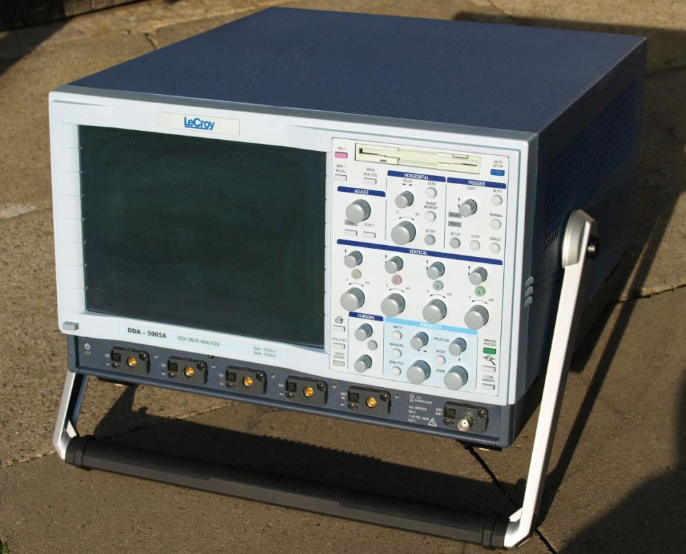
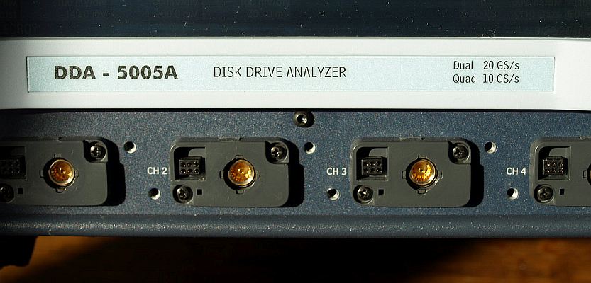
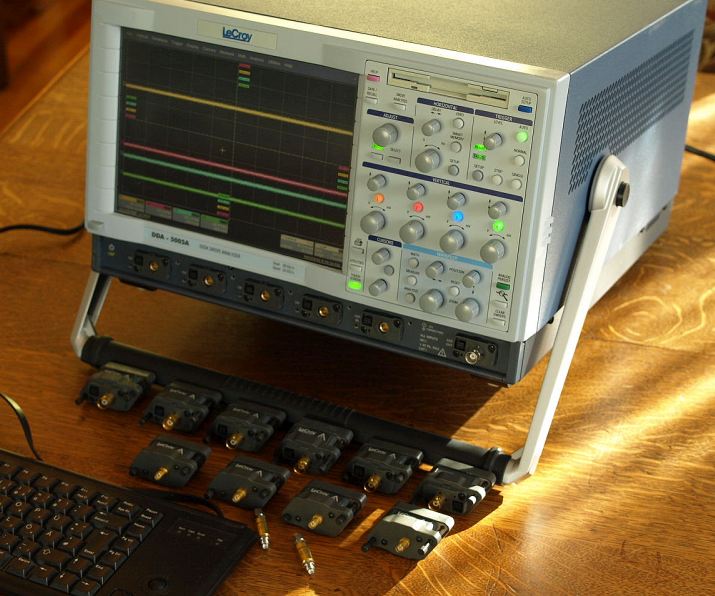
LeCroy DDA-5005A XXL
Disk Drive Analyzer - Oscilloscope5GHz - Dual 20GS/s - Quad 10GS/s - 50/100Meg Memory
enlarge
|
Four channel 50
ohm inputs, manufactored 2005.
The DDA (Disk Drive Analyzer) series is related to the SDA (Serial Data
Analyzer), wavemaster and wavepro series. Risetime typical 90 ps. The hardware in this family differs in bandwidth, memory, input amplifier, ADC, internal clock, CPU..... . Depending on year of manufactoring different build-in CPU and operating system. There are instruments updated with a faster CPU, newer operating system and actual firmware, depending in the owners interest to keep the instrument up-to-date. DDA XXL features are the combination of high bandwidth, signal quality, extra large memory and the disk drive analyzer software. A Disk Drive Analyzer is an oscilloscope with software for analyzing hard drives. The instrument can be used as general purpose oscilloscope - "DDA" it is an extra feature and doesn´t mean missing scope properties. For DDA and other applications a large memory is an advantage. With the 50Meg(4Ch)/100Meg(2Ch) memory a waveform can be sampled with 10GS/s(4Ch)-20GS/s(2Ch) and stored over some milliseconds. For example this allows the analyze of a high speed signal for missing pulses, distorted waveforms or jitter...., a "huge ZOOM". Sample rate and memory length can be set automatically or manual. When setting a low sample rate with full memory, it´s possible to record waveforms over a long time. Search the web for information about the family, there are brochures and catalogues online. Visit also the manufactorer website, you find there information and application notes about these instruments. Please read also the article wavepro 7300 XL. |
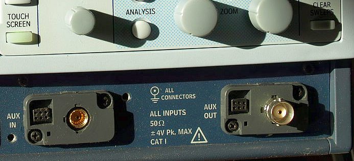
max. +/-4V peak input voltage limit
|
The input connectors are designed for 50 ohm signals and Wavelink series probes.
DDA, SDA and wavemaster series use this special 50ohm connector type, the wavepro
series has BNC connectors with switchable 1Meg/50ohm inputs.
|
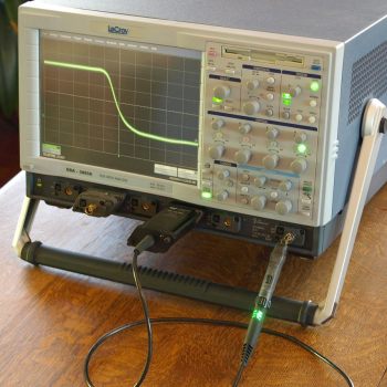
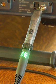
| Probe has a multi-color LED which is lighting in the color of the used channel. |
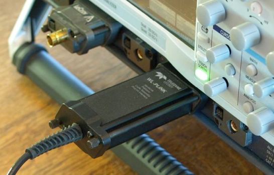
Wavelink probe body fits direct to the input connector, no adapter neccessary.
Probe head mounted on probe body. Probe head determines bandwidth and properties.
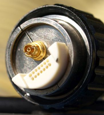
| Probe head in a conductive box, protected from electrostatic discharge and the sharp probe tips. Fast active, low capacitance probes are difficult to protect - user must handle with care. The probe head connector has a small dimension, head is mechanical fixed safe with a large screw. |
50 ohm RF connectors gold-plated
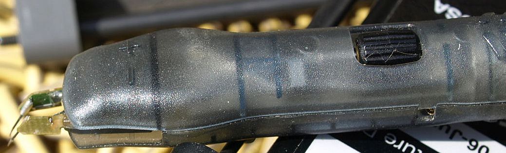
| Probe
tips are sharp and made of a super-elastic nickel-titanium alloy.
The adjustment wheel sets the distance between both probe tips. See the
catalogues for the probe portfolio, there are different mechanical probe solutions. With increasing bandwidth probe technology becomes more important. Each Picofarad parasitic capacitance reduces probe impedance vs. frequency. |
|
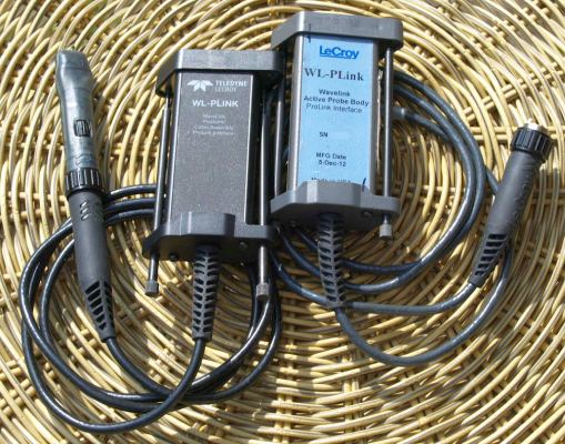
Wavelink and ProBus series active probes are recognized by the scope software.
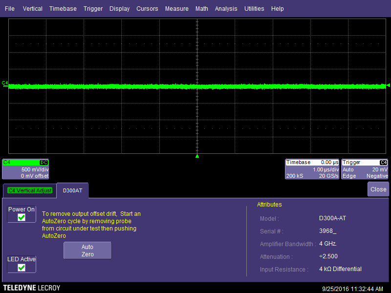
Probe head is a D300A-AT differential probe with 4 GHz bandwidth
(indicated by 5005A). Rise time 95ps (probe only), input
impedance 4 kohm Differential.
Software set automatically vertical scaling factor and units. Offset caused by the active probe nulled by the Auto Zero function. Scope recognizes actual and older probes. Installation of actual firmware recommended to be compatible with newer probes types. |
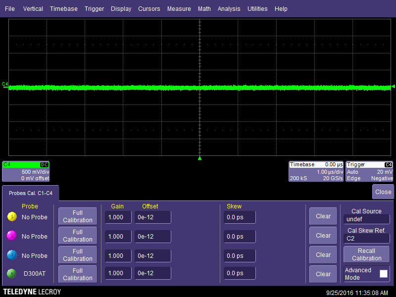
| Calibrate channels, active and passive probes individual in Gain, Offset and Skew. |
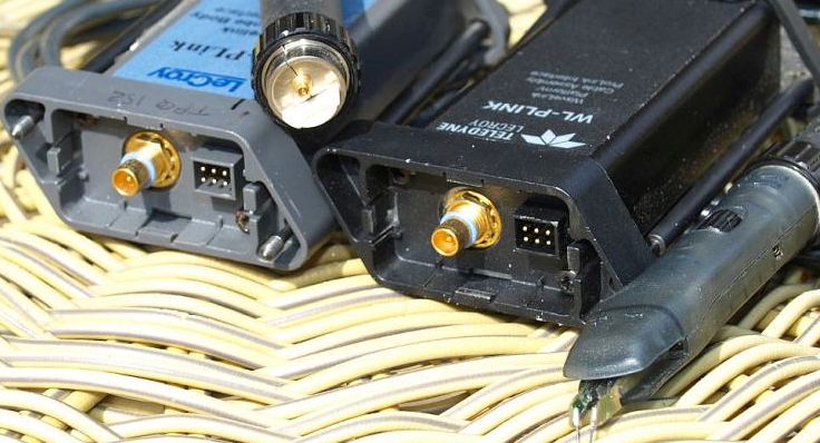
BNC or SMA connectors adapters available
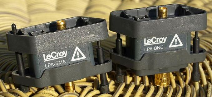
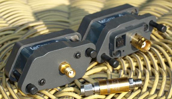
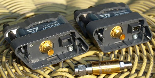
| The
right LPA-BNC adapter feedthrough the ProBus power and data-terminals
to the BNC-side. With this adapter it is possible to connect a BNC
cable or the older active probes ProBus series requiring 50ohm
termination. Connecting an active ProBus probe with 1Meg termination (for example current probes) requires an AP-1M Hi-Z-input adapter (not shown). The AP-1M is an active adapter with a 500MHz bandwidth. The AP-1M converts the input to a common known 1Meg input, passive probes can be connected to the AP-1M. The left LPA-SMA adapter does not feedthrough the ProBus. Maximum allowed input voltage +/-4volt on 50 ohms. Please consider - higher input voltage can destroy the inputs - prevent inputs from Electrostatic Discharge. In front shown a SMA DC-Blocker capacitor, useful for blocking accidential applied DC-voltages. A DC-blocker is not a 100% protection device, do not apply higher DC-voltages than the allowed +/-4volt on the DC-blocker input. In my opinion a DC-blocker is useful against "Accidential" not "Intentional" applied DC voltages. High bandwidth & signal quality & low input capacitance, difficult to protect. Such a high perfomance oscilloscope is not a beginners training device. Keep the input within the safe limits - it´s in the response of the user. LPA-BNC, LPA-SMA and AP-1M adapters are not often available on second hand market, prices can be high. An instrument & adapters together - seldom offered. There is also a adapter carrying-bag available. Original the instruments were sold together with adapters, after years of field-use, they can get lost. |
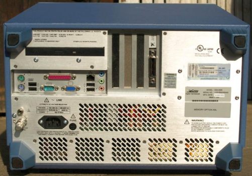
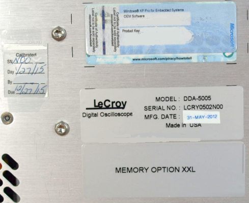
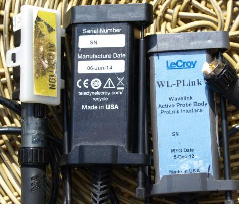
| Instrument
was build 2005 (serial-no. removed on the photo).
Unknown why the added sticker May 2012, may be a updated unit, has
newer operating system with a 2.5 GHz CPU. Memory option XXL was the largest available memory size, XL and lower versions having another memory hardware. Last calibration (performance check) valid up to 12/2015. I prefer the location of calibration stickers on the rear-side instead on the front-panel. |
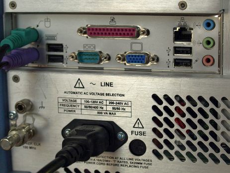
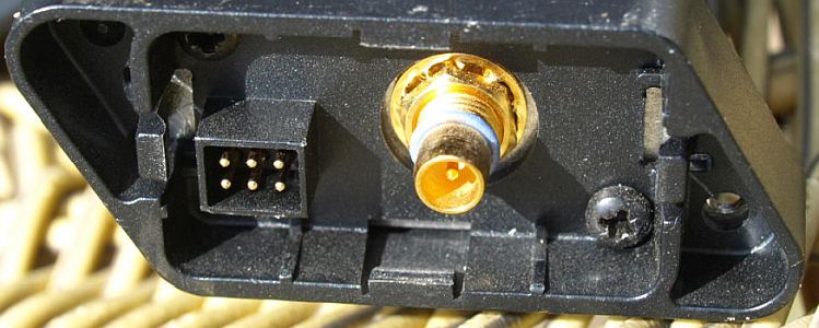
| The bottom left BNC connector 100MHz Reference Clock input. Internal there is a 100MHz precision OCXO, either the BNC REF CLK or the internal 100MHz drives a 10GHz DPRO phase locked dielectric resonator oscillator for the ADCs. Low phase noise design, timebase ageing and short time accuracy depends major on the 100MHz oscillator. |
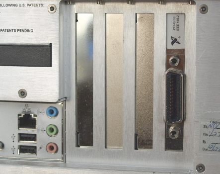
| GPIB Interface card for instrument control (optional hardware) or via Ethernet interface (standard). The Ethernet interface has the additional possibility using Visual Basic scripts, also calculations of the measured data can be done with that interface - see operators manual. |
|
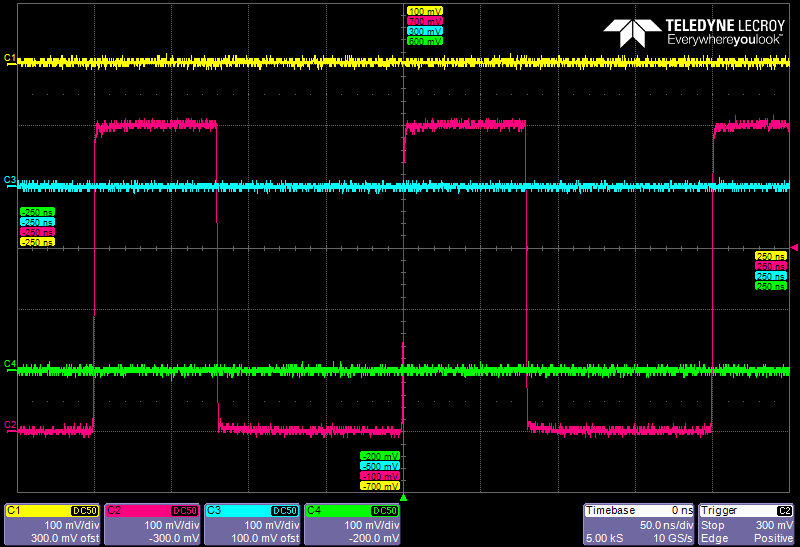
Colored standard printout with four active channels.
Timebase, sample-rate, trigger and channel vertical settings are always visible. Printouts can be done either full colored, black-white or with a printer-friendly white background. The border markers on the x-y axis can be switched off, perhaps the manufactorer logo can be also offed (not yet searched for the button). The pdf with 34 screenshots shows random selected instrument settings, pages from the help menu and some specifications about this instrument family. Shown instrument has standard software (no options), only option "DDA" installed. Help menu describes all options also the not installed. |
Some words about repairing such an instrument
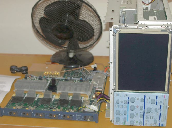
| Photo taken from a DDA-5005A XL (not XXL). Board is
sensitive against electrostatic discharge. Computer parts (not shown)
are mounted behind mainframe chassis. Scope electronic and PC
parts are shielded from each other. You must be sure when buying a defect instrument for a home repair. For example, if the board has an digital error, it can be time demanding. Difficult without having special knowledge and literature. Where to get programming files in case of a replaced programable IC or memory IC? I made a mistake to buy this defect 5005A XL. I can not locate the fault on this instrument and spent many hours, without literature no realistic chance. Difficult to track wires between IC´s on a large multilayer PCB. My gain for many hours, reading a lot of general electronic literature, getting much knowledge about the basic operating of such an instrument, the clock generation, many nice layout and mechanical details - it was a fine course in exploring a large digital-RF-analog PCB. It would be possible to change boards between two equal instruments, but for example I guess the amplifier, ADC boards are probably calibrated together with the mainboard, this would require a special recalibration. Changing boards has always another potential risk: when a faulty voltage level drives parts outside the absolute maximum ratings, both exchanged boards can be destroyed - result: two faulty cards. Doing such experiments is risky before being sure about voltage levels. Cross reference measurements between XL and XXL is another way to locate a fault, but finding a fault and a later successful repair is something different. A future task for quiet hours. |

miscellaneous gallery main gallery Impressum