Nonlinear DistortionsNonlinear distortions result in an amplifier from nonlinear curve characteristics of the parts. Linear distortions do not produce new frequencies. If the original signal no new frequencies are in addition-mixed, linear distortions develop. IntroductionNonlinear distortions have clear effects on the sound. They are a dominant factor source for disturbances. It is one of the highest targets with the development of a Hifi amplifier of keeping the nonlinear distortions small. Strictly linear conditions do not exist in electro-technology. Everything, whatever is called as linear, is nonlinear in reality. The question is only, which order of magnitude has the non-linearity? Much can be called confidently simplified linear. Transistors and tubes are particularly nonlinear. Depending upon operating point, the characteristics have a usually exponential character. In some characteristic sections also an overlaid square characteristic is present. Very linear elements are resistances. Some condensers are also still linear. Unfortunately the active amplifiying elements are nonlinear. The characteristics of transistors, diodes and tubes are clearly temperature and voltage-dependently. If the gain of these active elements would be linear, the building of an amplifier would be clearly simpler. The number of elements would reduce drastically. But nature is merciless in this regard and gives no consideration to the desires of a developer. Nonlinear distortions make visible |
|
|
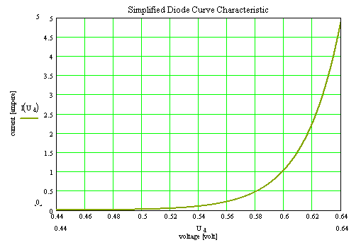
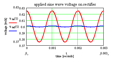
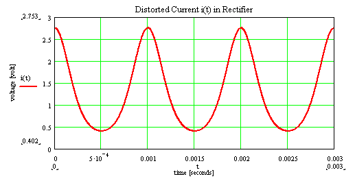
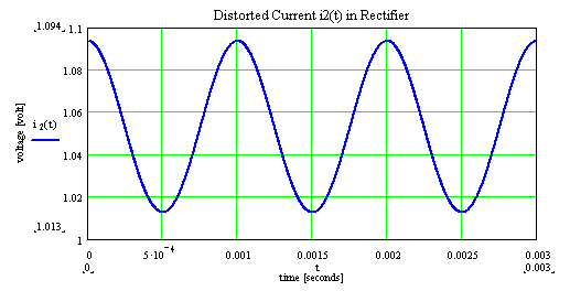
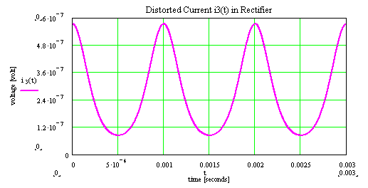
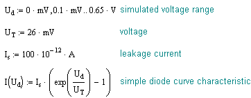
As an aid here a model for a simple diode serves. The nonlinear distortions caused by the diode, are made on the basis the curve characteristics visible. The diode characteristics is based in a simple model of a diode. At the diode a sinus-wave voltage with offset is applied. The resulting current by the diode is not linear any longer. It contains new frequencies. |
|
|
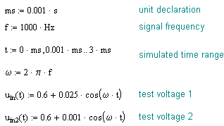
parameter of simulation |
