|
Amplifier
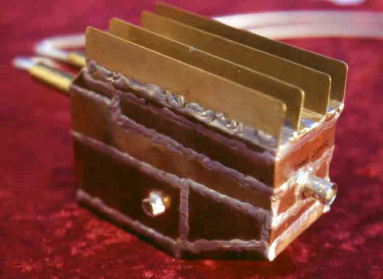
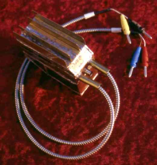
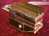
in completely soldered copper housings. The housing is a good heat
dissipation. At the side soldered entrance to the offset trimmer. The
closed copper housing is a very good shielding against disturbances.
|
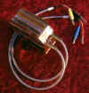
On the top
side soldered on brass cooling fins. The inlets are laid out as shielding
capacitor with a metallic hose. Up to now I did not repent that to solder
yet. (tin opener - no thank you)
|
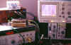
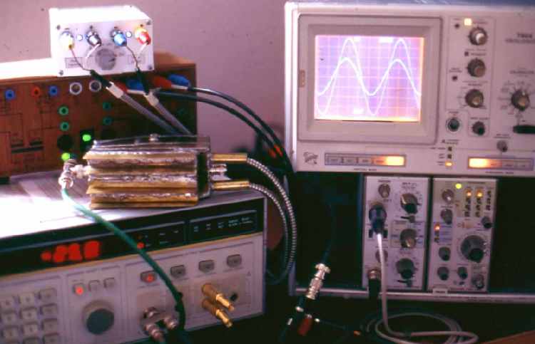
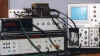
Measurement 1 - measurement assembly at 1 MHz and 18mV on input. Equipment
HP3336B sine level generator, Tektronix
7904 scope, simple regulated power supply.
|
 |
frequency response
characteristic:
7 MHz bandwidth -3 dB at 60 dB
0.5 dB gain variation over 4.5
decades
positive low frequency
phaseshift by correction and AC-coupling
(input amplitude 14 mV, supply
+/-20V)
|
|
What did I
forget? to adjust the gain to exactly 60.0 dB - now them are 59.7 dB - if
it is disturbing for you, then send me nevertheless please a tin opener
and a box italian Ravioli, then I perhaps correct it. The phase shift for
low frequencies is too large, the AC coupling works too late - design
remains in such a way and won't change.
A note for
phase shift and at the same time a memory of the school medicine: with
very high frequencies the phase turns beyond the magic 180°, and the
reinforcement is still larger than 1 - where the oscillation remains? The
phase shift at the "genuine point of inverse feedback" of the automatic
control loop is crucial. This sits deeply the inside one the amplifier.
The phase shift at the point of inverse feedback is again corrected by the
frequency response of the inverse feedback networks - however the fun
begins exactly there to build an amplifier and ends there the fun often
also again. The amplifier shown anyhow could be further improved in its
frequency response by very intensive corrective measures. This amplifier
however certainly not more - however the next guarantees.
|
|
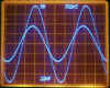
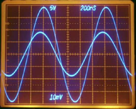
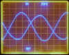
Measurement 1- scopescreen with 1 MHz and 18mV. An visible wave distortion
can't be noted. Tektronix scope
7904 using
7A26 amplifier and
7B85 timebase.
|
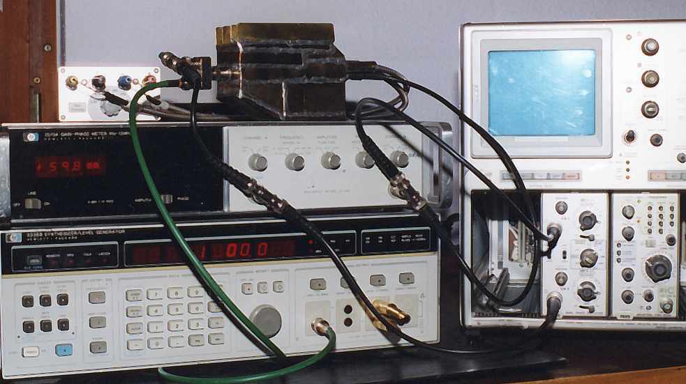
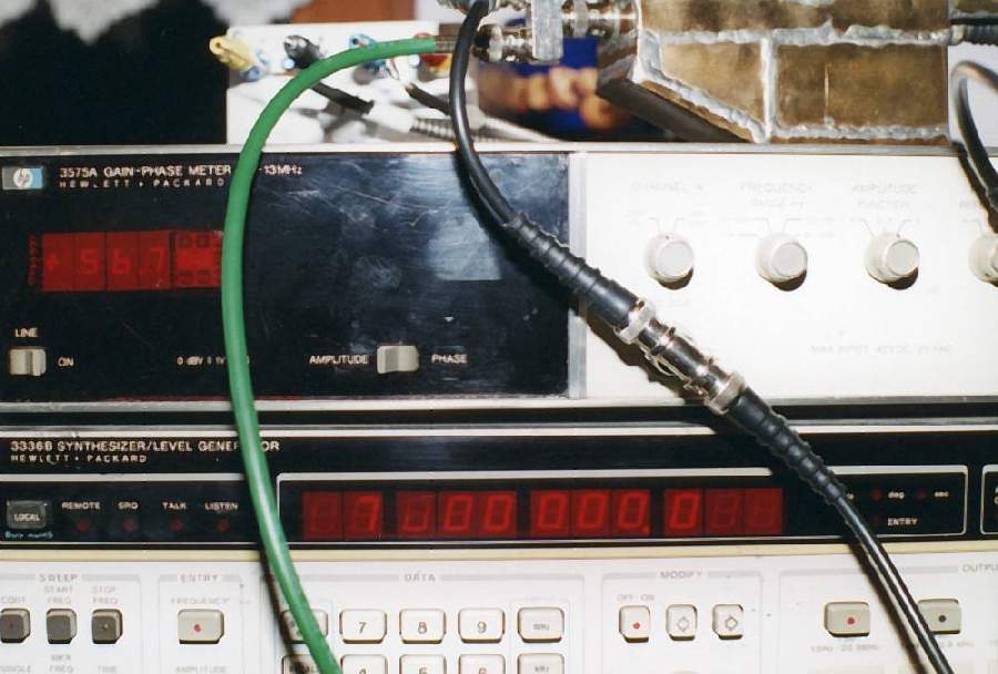
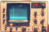
Measurement 2 - 1 kHz and 59.8 dB. Recording the bode diagram with a
HP3575A, capable to measure a maximum of 13 MHz. Direct flashing was a
wrong photographing.
|
Measurement 2 - the -3 dB
bandwidth, frequency of 7 MHz, gain 56.7 dB. This time without flash.
Adjusting balance of room and scope illumination it's a hard task.
|
|
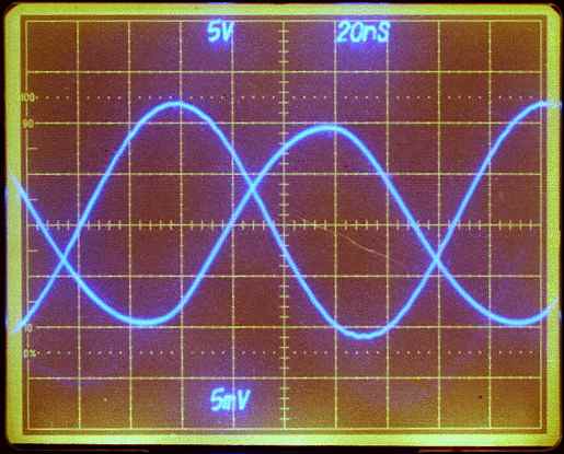
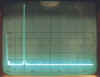
Measurement 2 - scopescreen with a bandwidth of 7 MHz. Amplitude input
voltage 14 mV. Power supply voltage +/-20 volt. Output signal clearly
disturbed.
|

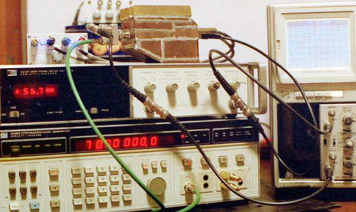
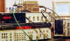
Measurement 2 -flashing under this angle was not a good idea. Through the
short eposure time not all numbers can be showed faultless. The video
cable is terminated with the generators impedance of 75 ohms.
|
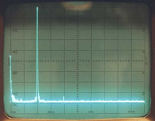
Measurement 3 - applied a clean 10 kHz sine to the amplfiers input,
outputs +11dBVrms (5 Vp). 2nd harmonic at 20 kHz and -84 dBc. Distortion
0.006%. 1000 seconds sweep time.
|
|
Measurement 3 - easy to see close to the carrier there are mixing products
probably caused by line AC of the external amplifier power supply.
|
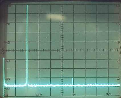
Measurement 4 - output amplitude 20 dBVrms (28 Vpp) 10 kHz under a load of
390 ohms. The amplifier isn't impressed very much. K2 keeps in comparison
with measurement 2 almost unchanged. K3 increases to -80 dBc about 0.01%.
|

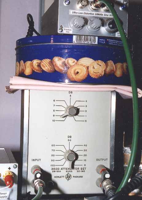
Measurement 3 and 4 - An
HP350D using as attenuator for the ultra low distortion 10 kHz signal.
The attenuator has an impedance of 600 Ohm and is an excellent choice for
this purpose. This time I was lucky with the direct flashing.
|
|
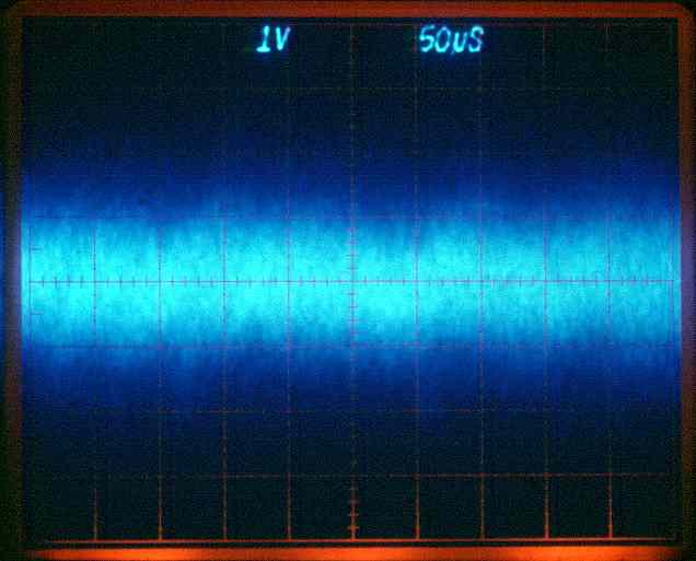
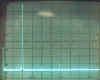
Measurement 5 - shows output noise of the amplifier with an open input,
only terminated by a internal 2.2 Meg resistor. The thermal resistor noise
and the added bias input currents are amplified by the wideband 60 dB
gain.
|

Measurement 5 - output noise with a time base of 2ms/div. Visible single
peaks up to 2 volt. The RMS value of this noise can be wonderful adjusted
by the choice of the source impedance. For this photo the Illumination has
been reduced.
|
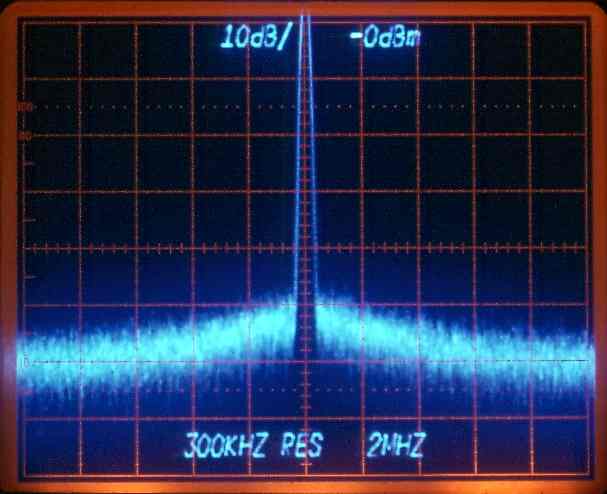
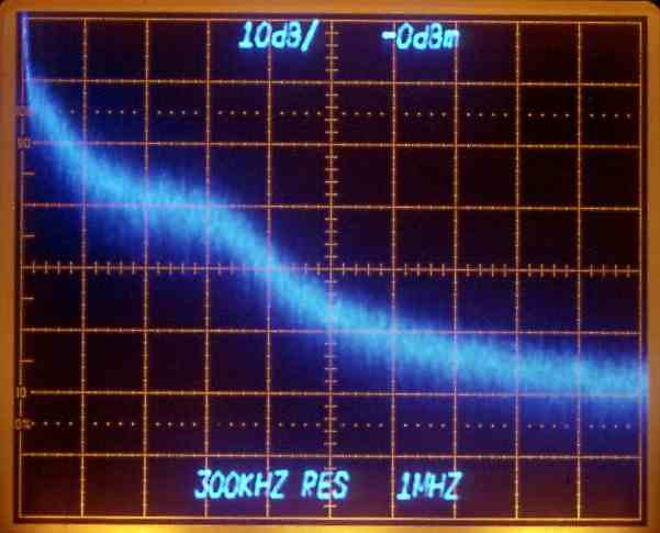
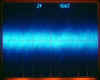
Measurement 6 - spectrum analyzer Tektronix
7L12 with an open input. Top refence line level 0 dBm. The peak
in the middle is the DC center frequency. One division 2 MHz and 10 dB
vertical. Dynamic analyzer range about 65 dB.
|
|
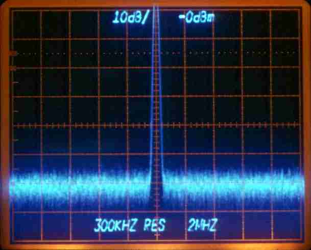
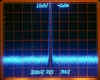
Measurement 7 - analyzer settings as in measurement 6. The amplifier is
connected to the analyzers input. Amplifier input terminated with a 50
ohms resistor. Less additional noise caused by the amp.
|
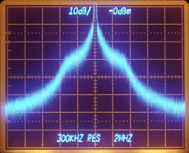
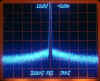
Measurement 8 - amplifier grounded with internal 2.2 Meg only, resulting a
noise fireworks. Please note the photo's straight lines in the border
areas. Minolta's MD50 macro objective works fine.
|

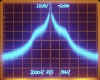
Measurement 8 - input 2.2 Meg. New analyzer settings, the center frequency
moved on the left side. Span reduced to 1 MHz/DIV. At higher frequency
limits the bandwidth of the amplifier additional noise.
|