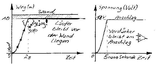
What are Slew Rate, Open Loop and Bandwidth?Slew Rate:imagine you are a good 100 m meter runner. Somebody applies you an blindfold and put you 10 meters in front of a concrete wall. You are in start position. Ok, I care for you, the somebody starts instead of you. You stand beside the somebody and you are doing the starting shot. "Somebody" runs with full power, all bystanders: "go, go go". What happens? Full braking in front of the concrete wall. The somebody will get bad headache. An amplifier behaviors like the runner. A runner starting with full power, blind and don't know where to go. A fast runner needs 10 seconds for the 100 m. A fast operational amplifier slews to about 4000 V per microsecond. But also an amplifier reach his concrete wall, the rails of the power supply. That's the maximum limit.
Figure 1: an
indicator for the speed of an amplifier - slew rate.
Slew Rate can be measured by checking the most steepest rise of an square wave response. It's common used in electronics to check the rise time between 10% and 90%. The runner need for the distance of 1m to 9 m about 1.5 seconds. So the runner achieve a slew rate of 8 m per 1.5 seconds. We normalize it to 1 second, resulting in 5.3m/s. The same calculation can be done for an amplifier. We define 10% and 90% to 1.3V and 11.7V. Amplifier need for example 4 nanoseconds. Slew rate can be calculated as 10.4V/4ns. It's common used to normalize a slew rate to one microsecond. We get a high slew rate of 2600 Volt/microsecond. An audio amplifier attain a dimension of 0.5 V/µs up to 100 V/µs. Of coures there are some other ciritical issues for the speed of an amplifier. For example the bandwidth - bandwidth and slew rate are closed combined, a high bandwidth is only possible if a high slew rate exists an vice versa. |
||
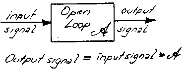
The Open Loop amplifier gainis a very important characteristic to characterise an amplifier. Amplification mattered a small input signal should be amplified by a defined fix factor. Generally most amplifiers having a high open loop gain. There are some operational amplifiers, with a gain of 10 millions. This connotes: this amplifer needs only a little voltage of 100 nanovolt to reach an output voltage of 1 Volt. Logarithm and decibel: it's not easy to calculate always with high numbers, therefore for gain calculations we use a transformation to decibels. for 10 millions resulting in 20*log (base of 10) of 10 mio = 140 dB. An audio amplifier has a high open loop gain, let us consider he reach 100 dB. So an little voltage of 10µV on his input is quite enough to reach an output voltage of 1V. This gain is too much. Consider your CD player delivers 500mV, the amplifier with his gain of 100dB (100.000) = 50000 Volts at the output. No, that's not possible. It's the same situation like the 100m runner, the amplifier listen to the start signal, doing a maximum amplifiication until reaching the rails. The first meters the runner start running with full power, but close before reaching the wall, somebody needs to tell him: "stop stop stop". Also the amplifier needs a "somebody" to tell him to stop, not to reaching the rails, for an amplifier this "somebody" is called "negative feedback". It's not the task of the "somebody" to make the runner going slowly by giving bad food to him. No, the "somebody" must coach the runner to stop very fast. Same task for the negative feedback, helps to stop abrupt. The "somebody" and the "negative fedback" control the runner and the amplifier. Reducing of gain by negative feedback for a wished fix gain: an amplifier has two inputs, an inverting and a noninverting. It's best to do a mathematical model for a simple control loop. |
||
|
|
|
|
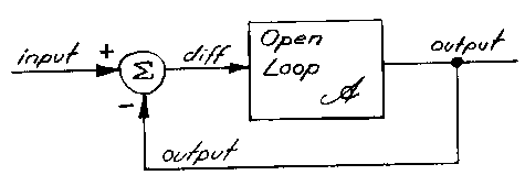
| Figure 2: already established, the input signal amplified with the high open loop gain A, the result is always the output signal. | Figure 3: the negative feedback leds to a difference signal. In this case the input signal and the output signal forms a difference signal "diff" and only the small diff signal will be amplified by the open loop gain. | |
The right figure is very interesting. Remember
the ideal amplifier: the output signal should have exactly the same shape
as the input signal. An ideal amplifier has an infinite open loop gain.
This matters the diff signal must be zero. It's a conflict between theorie
and reality. An infinite open loop gain is never possible, only a high
open loop gain can be reached. The question is: "how much". A low open
loop reach to a lower output signal than wished.There is always a difference signalImagine, a input signal of 1V and a difference signal of 1mV. Thus the output signal calculated to 999mV. It's easy to calculate the open loop gain: 999mV divided by 1mV = 999. A gain of 999 = 59.99dB. Oh, the amplifier does an error! -yes- But I don't want an error, there is a gain error of 0.1 percent. What helps? we increase the open loop. the higher the open loop the lower the gain error on the output. The amplifier in figure 3 is a closed loop gain of "1" amplifier. The closed gain is the "wished" gain. How to get for example a closed loop gain of "ten"?we don't feedback the whole amount of the ouput voltage to the difference element, only a part of it. |
||
|
Figure 4: Feedback Factor Beta, makes it possible to adjust a higher gain than one in figure 3, up to the open loop gain of figure 2. The shown figure 4 is an elementary basic in the automatic control engineering. Also audio amplifier obey these rules. They don't have their own audio laws, like some people want. On the left in figure 4 there are three equations, derived from the equivalent control diagram. Target, to derive with these three equations is the single equation describing the response (output/input) of the closed loop amplifier. One of the most important equation for an amplifier. If we want a closed gain of 10, we need adjust Beta to 0.1. Possible by a resistor divider supplying the "inv." input by only 10% of the output voltage. Consider 1V applied on input and an open loop of 1000. 10V on the output, the diff signal must be about 10mV. Let's calculate with the new equation: 1/(0,1 + (1/1000)) * input = 9,90099 Volt. Oh no - we want 10V, the error reaches already 1% percent error. With a gain of one it was only 0.1%. Next step increasing gain to 100. 1/(0,01 + (1/1000)) * input = 90,90099 Volt, instead of 100V. Already 10% error.Next step increasing gain to 414: 1/((1/414) + (1/1000)) * input = 292 Volt anstatt 414 Volt. Decreased to 2/3. Bad. We reached the point of the bandwidth. The Bandwidth of an amplifier, is the point in the amplitude response with an adjusted closed loop gain in the region of the open loop gain. |
||
|
Figure 5: the bandwidth is definded as a loss of the outut voltage of 1/sqrt 2 to the wished output voltage. These relationship can be calculated by the open loop equation in figure 4. An amplifier with an open loop of 60 dB reach the bandwidth by a wished gain of 414. It's easy to see, for a high gain the open loop should be much higher than the closed loop gain. The open loop is not constant over temperature and frequency. With an increasing frequency the open loop decrease. The equation in figure 5 is a model for further discussion under an acceptance open loop vs. frequency. The purpose is to demonstrate the close relationship between bandwidth, slew rate, open loop and closed loop. |
||


