27.Ck Compensation Part Four


Shows Influence of Compensation Elements


Remember the Compensation Schematic


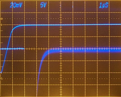
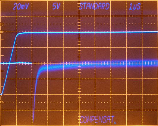
Compensation schematic for a flat compensation of bipolar and unipolar output configuration.  xx there is the switch (not drawn) disabling the special compensation. Special compensation shows higher influence on bipolar than unipolar configuration. xx and xx connected with the xx, xx on the xx network.


Following examples use DAC xxxx with Amplifier xxxx for -10V to +10V Full Scale Step

Difference between Standard and Special Compensation


Best possible compensation using only xx xx, others switched off.


Most flat compensation using the whole compensation network.


Special Compensation Values - Examples for variation of compensation elements

.
Best possible compensation using the whole compensation network.
xxxx = xx pF
xxxx = xx pF
xxxx = xx pF

Changing xx


xx = xx


xx = xx

xx changes waveform very softly, bending waveform.

Changing xx


xx = xx


xx = xx

xx changes waveform softly, create or damp a wide spreaded pole.


Changing xx


Aperiodic Settling with xx = xx, Settling Time 2.6µs


Increasing xx from xx to xx, settling time decreases from 2.6µs to 5µs.


Decreasing xx (only xx change), very much influence on the pole, settling time decreases to 3µs.
xx alone can't compensate the waveform of the most top photo.


Changing xx

Varying the distance of xx changes the influence of the special compensation network.
Setting xx acts like switching off the special compensation network.


back


Impressum und Haftungsausschluss