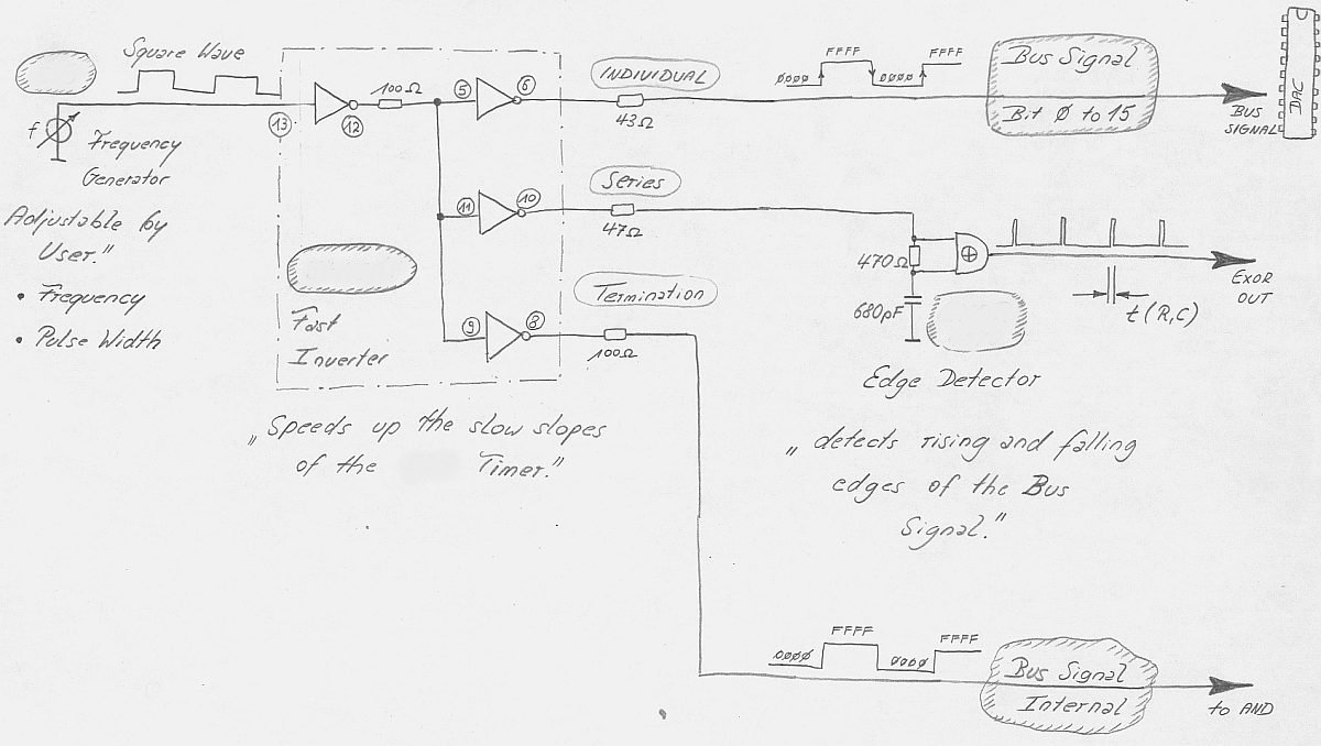
| DAC datasheet says
when the DAC registers operating in the transparent mode the deglitcher
don't work and higher glitches occurs in the output. The deglitcher
circuit should be activated now by using both registers. |


|
|
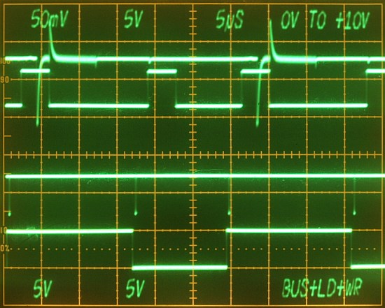
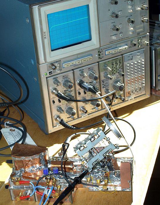
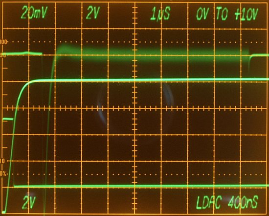
Full Scale Step 0V to +10V
Top Trace - Gated Settling Window Middle Trace - DAC output (2V/DIV) Bottom Trace - Load DAC, rising slope on first division, falling slope after 400ns tld . |

|
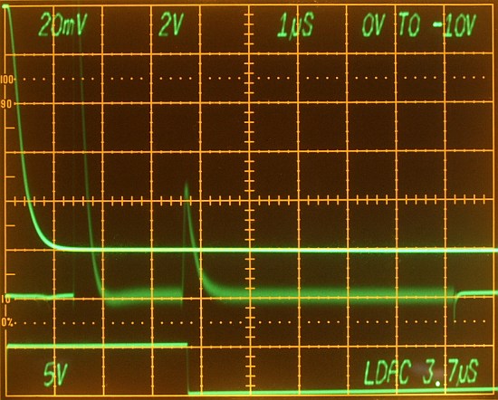
Full Scale Step 0V to -10V
Top Trace - DAC output (2V/DIV) Middle Trace - Gated Settling Window Bottom Trace - Load DAC (5V/DIV), rising slope on first division, falling slope after 400ns tld . |

| Glitch occurs - shifting the
falling Load DAC edge within the gated settling window to 3.7µs
shows the glitch. Let's calculate: 2.5 Divisions under
500µV/DIV at the Settle Node (1mV/DIV at the DAC Output) A 2.5mV
peak Glitch under a full scale step. |