9.Diode Bridge Part One


Current mirror transistor array.


Current mirror PCB.
Power supply -5 volts bypassing with ceramic capacitors.


Small -5V PCB soldered on ground with ceramic capacitors.
Capacitors from 4.7µF down to 10nF types.


Baseline potentiometer and corrosponding resistor mounted close to the current mirror.
This small plane should have a low impedance to ground.


.


Bottom ground plane connected with top ground plane.


There are four paralled 3321 (3k22) resistors soldered on the -5 volt plane.


Left - a small piece of copper on top of the four 3k22, a soldering terminal for the base of Q2.


A ground wall around base of Q2.


Base potential enclosed with a massive ground.


Diodes mounted close to the emitters, they carry fast transient currents in the emitter.


The yellow teflon isolated wires are the temperature control.


Shield over the -5 volts plane and over the yellow heater wires.


Front side closed with ground. Like building houses.


Heater transistor
I have many of them, ok for simple DC applications.
Curve Tracer settings 2mA/DIV, 10µA base step


Soldering the small epoxy with a 60 watts iron.
Control amplifier


Selection of two 10 kohm resistors with equal values.


Heater control. The 1k5 resistor with the long wires is used for the temperature selection.


  • Left side - Collector bypassed with a 4.7µF X7R, protection diode 1N4148, 1kohm base resistor.
  • Middle - Input -5 volts blocked with 4.7µF X7R.
  • Op amp output comes with a teflon isolated wire, it's better to place the 1k close to the sensitive base instead of close to the Op amp output.
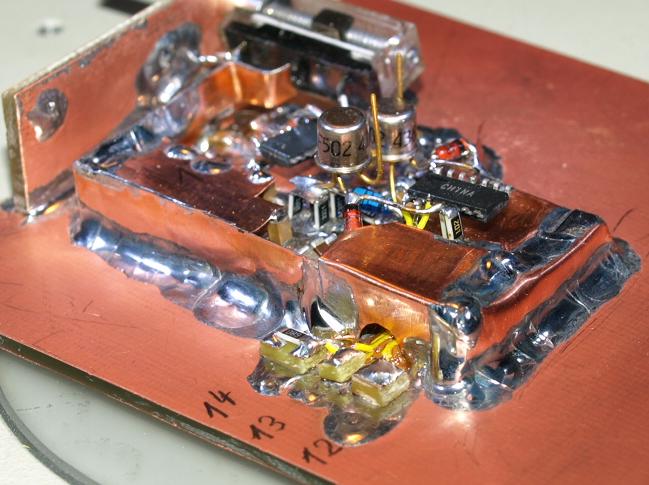
I've tried the temperature control and the circuit works.


Middle - new ground plane supported by capacitors.


Middle - low noise -5V voltage regulator  with a SMD voltage divider soldered direct on the part.
Unfortunately I don't have the fixed -5 volts version currently in my lab.


Heater operates


Middle - regulator with ground shield.


Front - ground wall.


Voltage regulator on a PCB from another project.


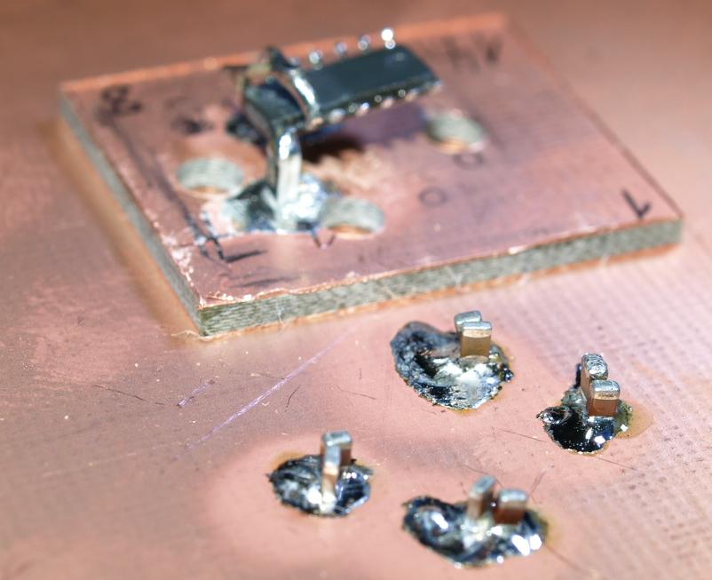
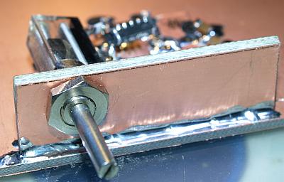
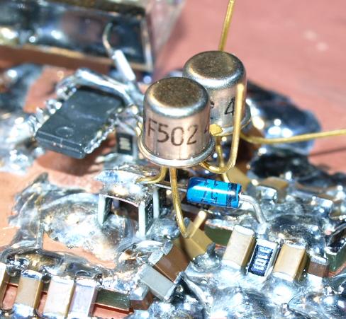
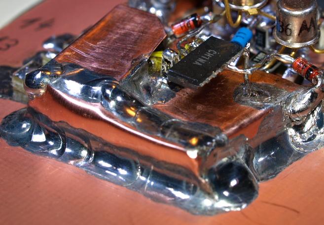
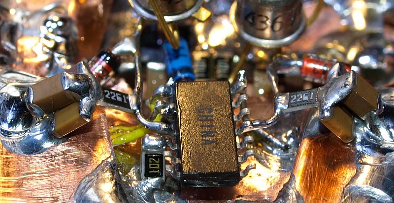
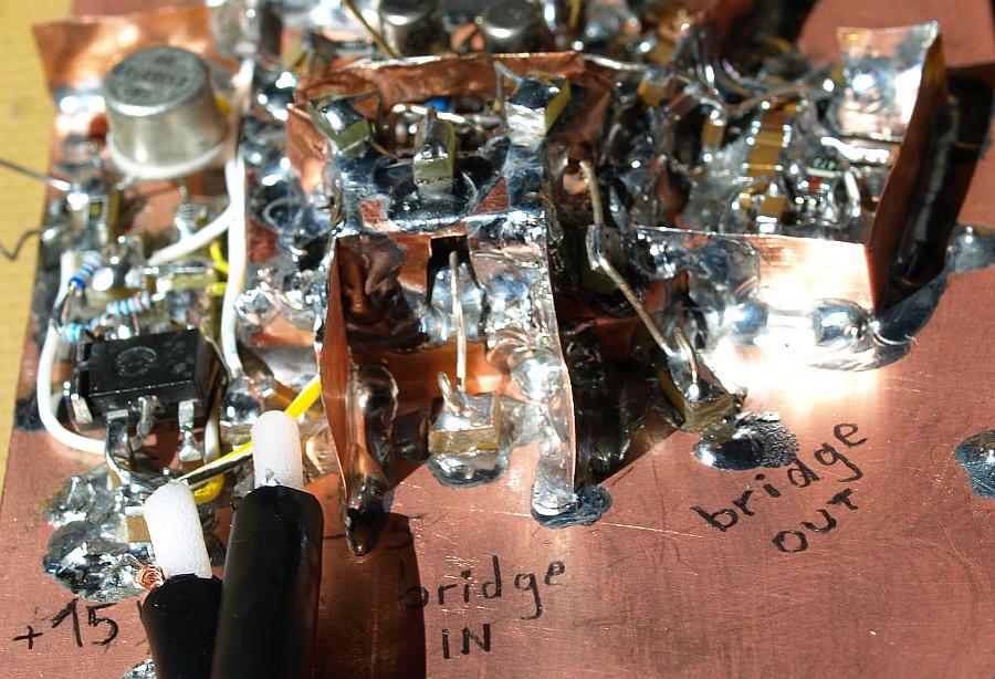
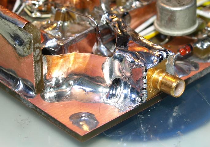
Voltage regulator mounted.


Top - over the array a +5V rail made of copper soldered on the ceramics.
5V power comes from right side.


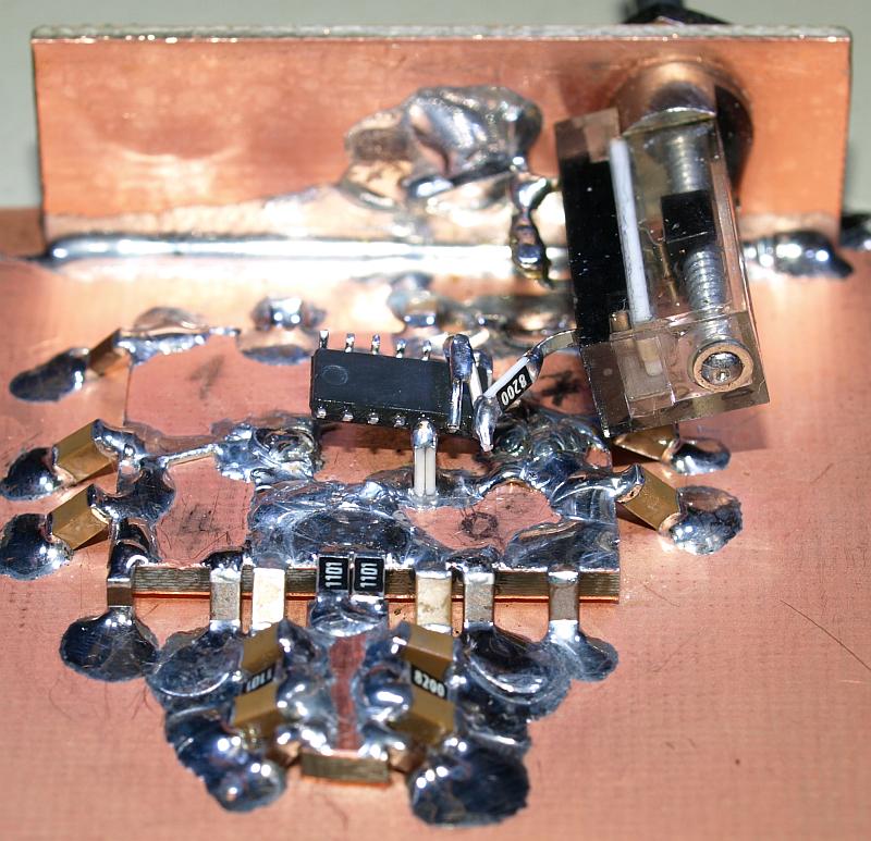
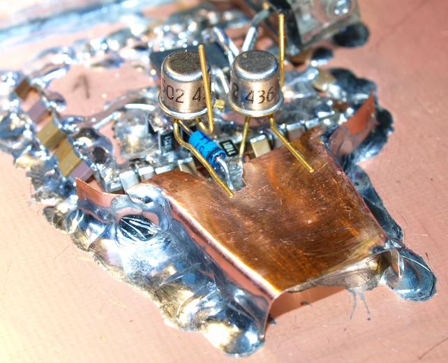
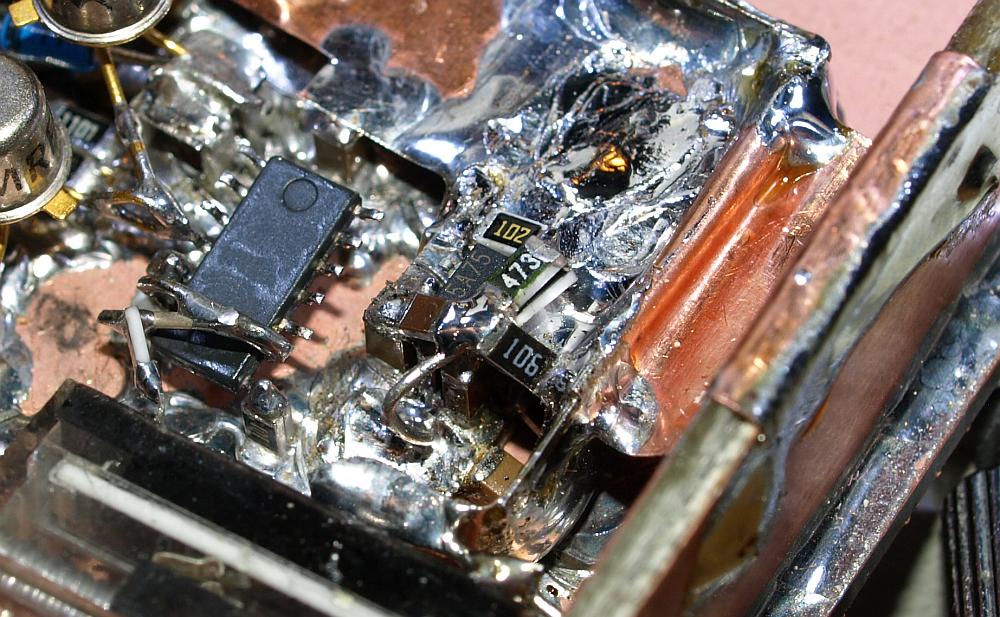
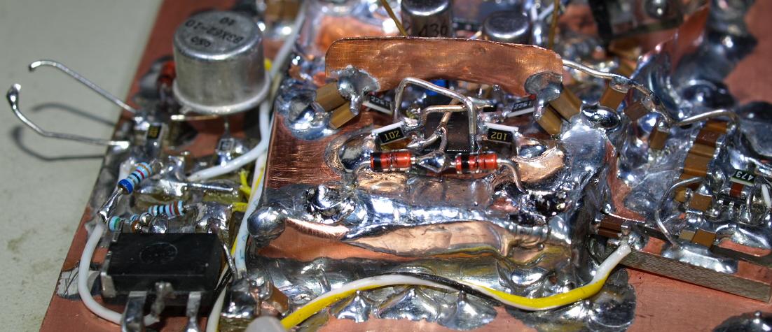
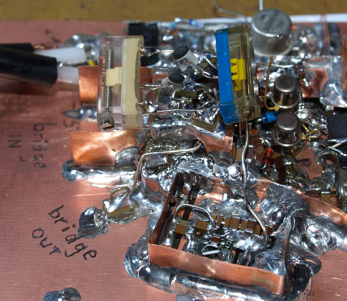
Diode array bridge connection.


Middle - 1N4148 - two protection diodes for the bridge input.
Left side - two wires for grounding heater transistor base.


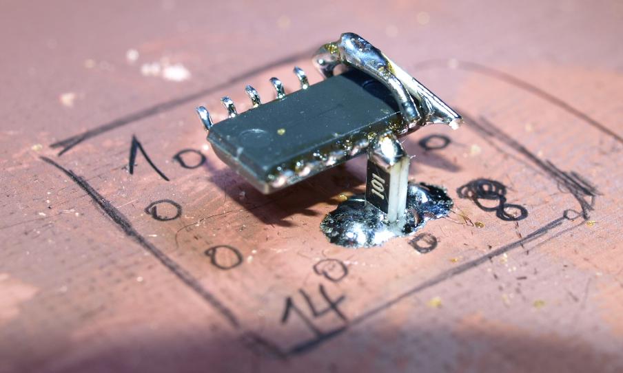
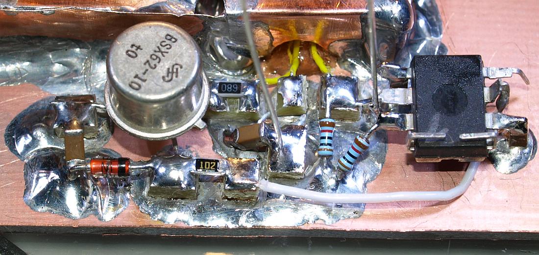
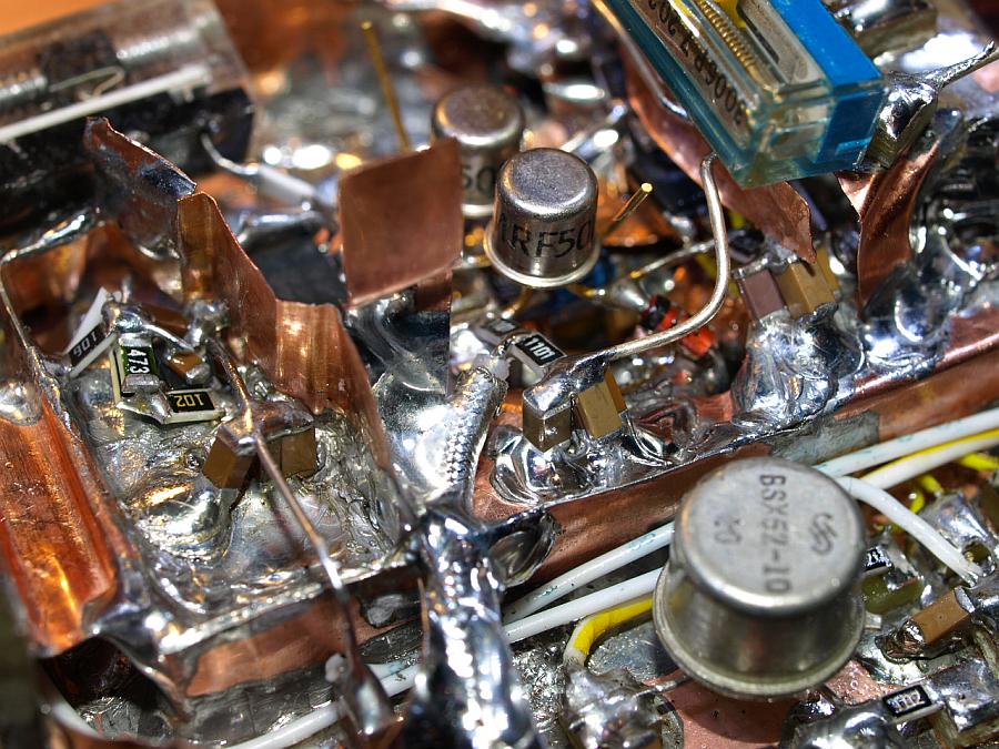
Middle - two 1k1 resistors (1101) and power supply bypass.


Middle - bridge input terminal.

Two wires up to the sky are PIN 4 and PIN11 for Skew-Compensation and AC-Balance.


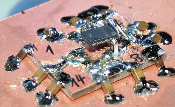
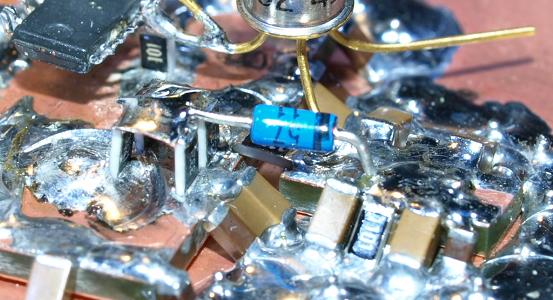
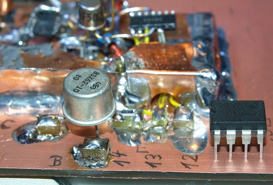
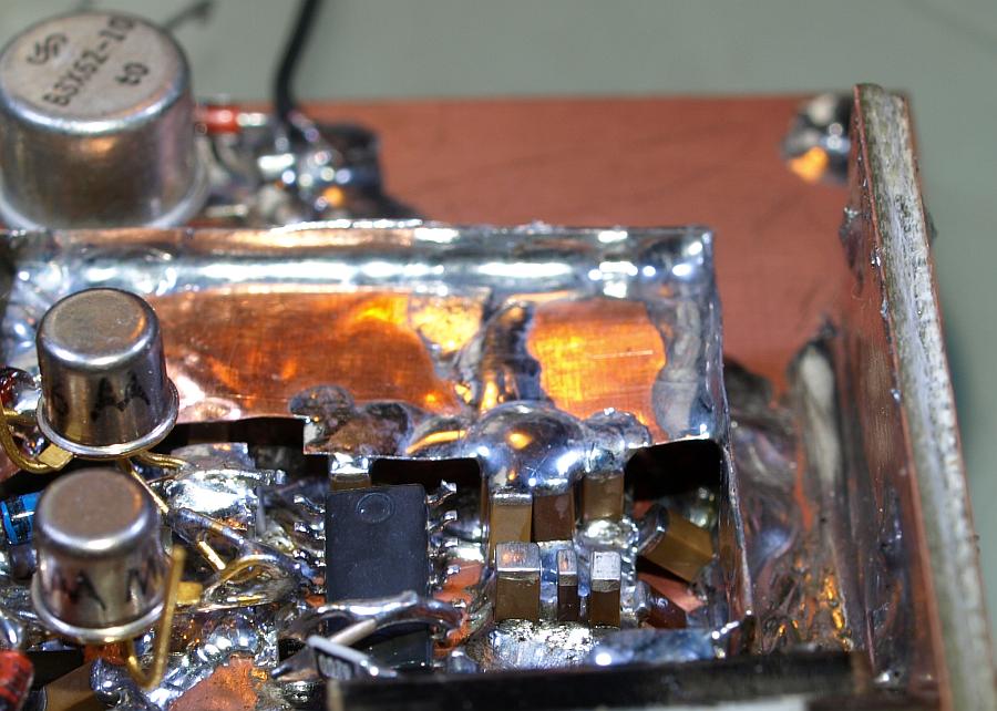
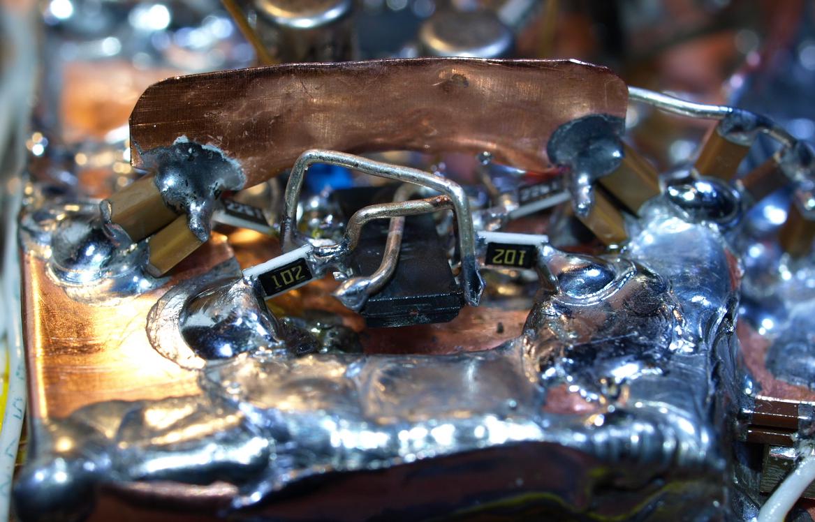
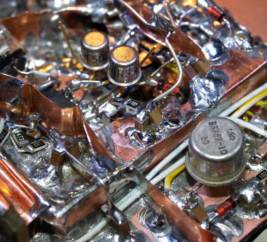
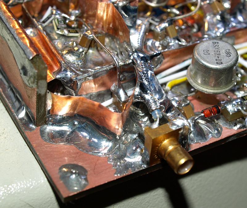
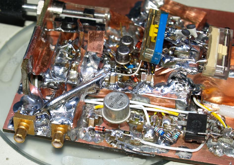
Middle - the diode array is fully enclosed with ground.


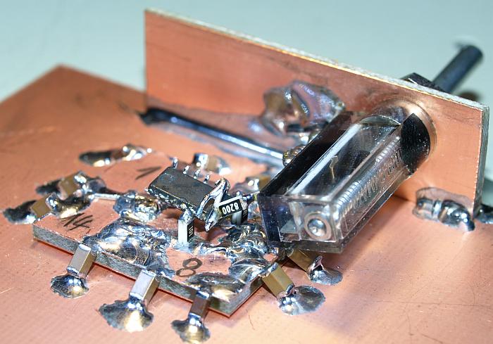
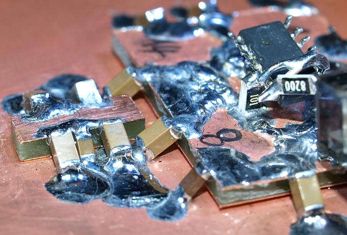
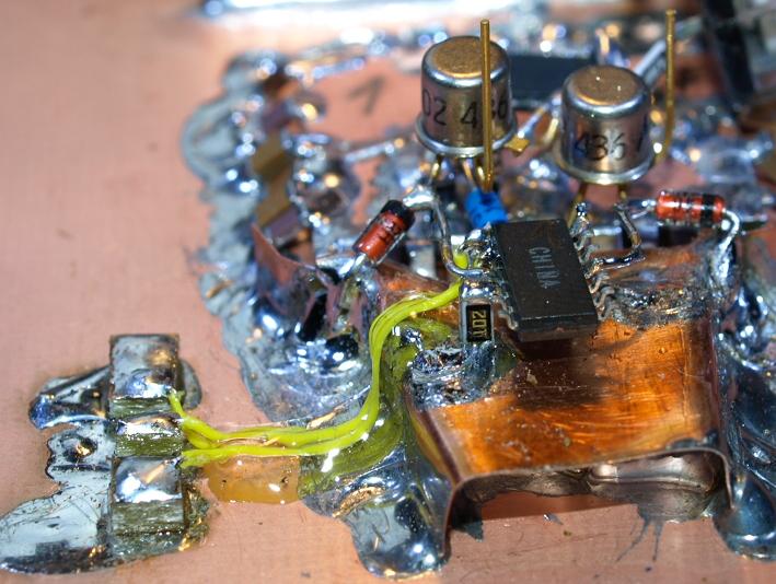
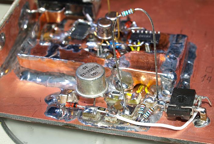
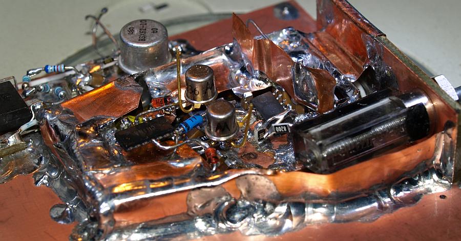
Top - Skew and AC-Balance soldered.

I hope never must change the diode array, it would be a horror. 


SMB Trigger Generator Input.


Coaxial cable type with solderable shielding.


Trigger input fully encapsulated.


Left side - coaxial terminal for the trigger supply.


FIRST TEST


Without taking any care of good probing - the first run.


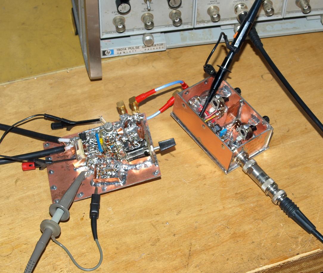
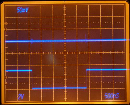
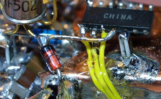
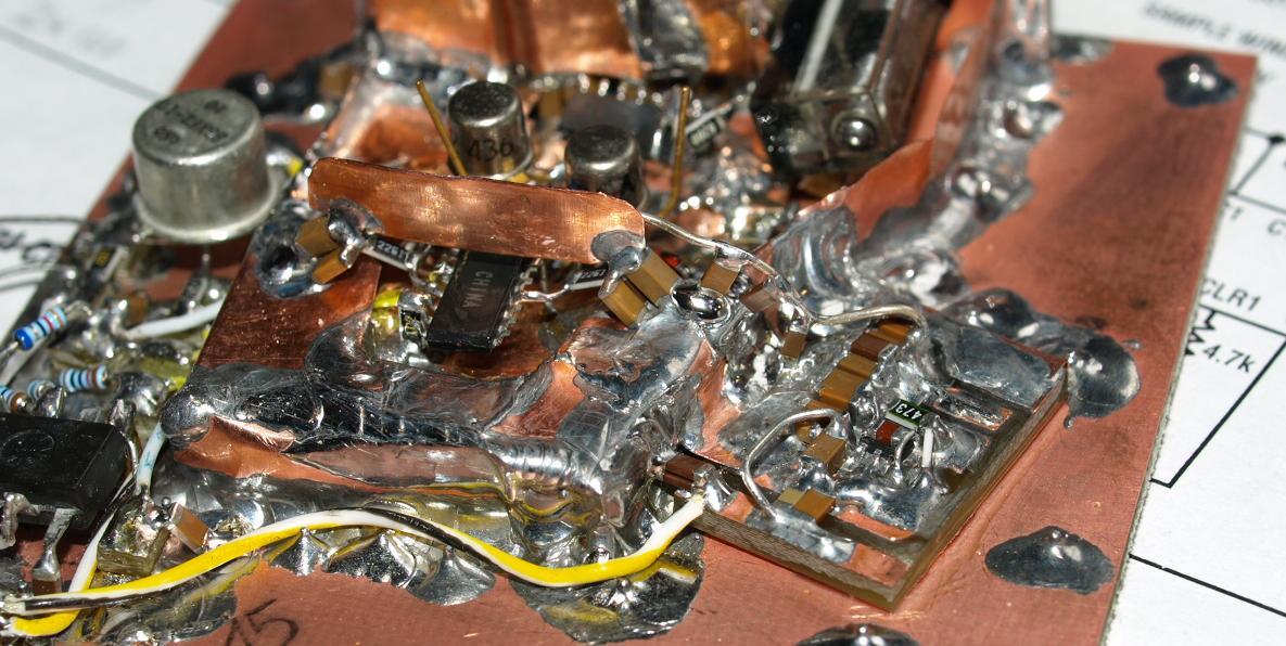
THE CIRCUIT WORKS !

It made me a not unhappy, everything is soldered correct and all parts operating.

Using a 1:10 probe on a 7A26 (200 MHz bandwidth) after adjusting Skew-Compensation and AC-Balance.


back


Impressum und Haftungsausschluss