

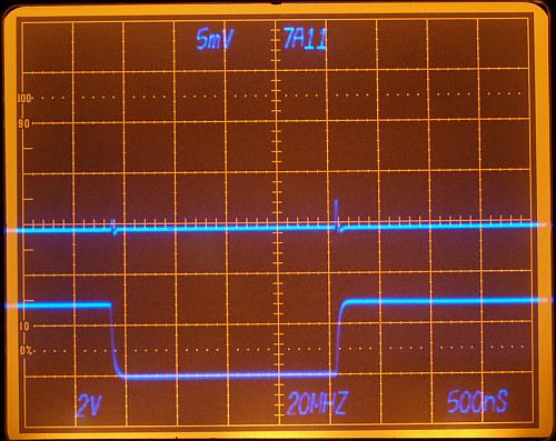
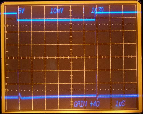
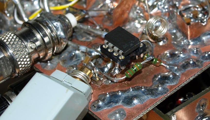
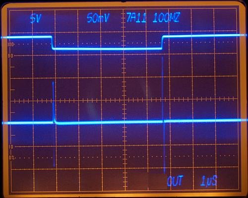
| Bridge Output - 7A11 amplifier shows spikes, 7A11 works with a 100 to 150 MHz bandwidth and approximately 6pF probe capacitance for all ranges. In this measurement the sampling window signal has an 43 ohms series resistor in it's output, this slows the slope. |
|
The bridge output should not be loaded with too much capacitance -
reduced measurement bandwidth decrease spike height - and decrease also
measurement speed. I'am disappointed, the spike will be too high after amplifying.
|

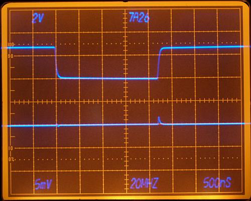
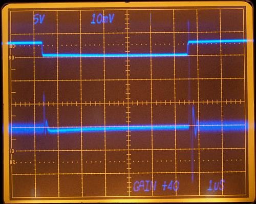
| Residue Amplifier xxxx not a good choice for high signal frequencies with Av=+40. Peak 13mV ( measured with 7A11 20MHz BW). Left edge of the sampling window starts with a slowly slewing slope - thermal effects? |

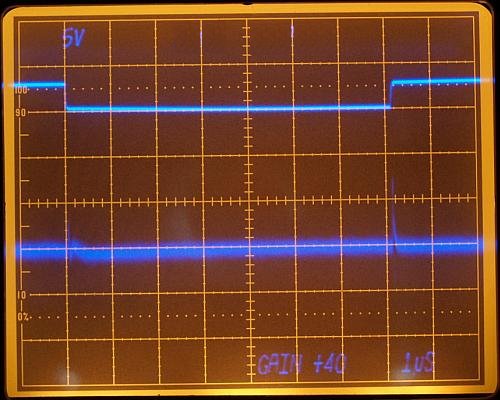
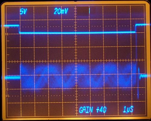
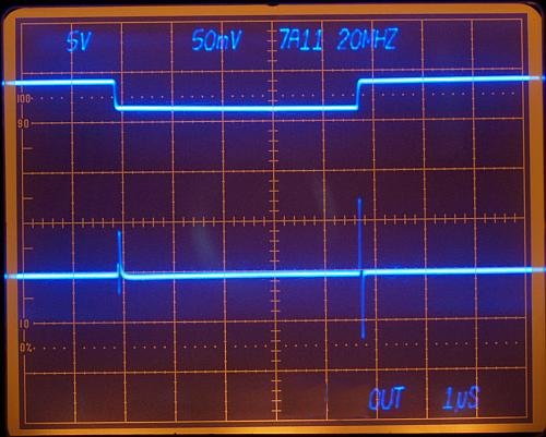
| Residue Amplifier xxxx - fast CFA, Peak 50mV. Rf=1k3 should be readjusted for Av=+40 gain, 2 (measured with 7A11 20MHz BW). Under the 10mV/DIV deflection good visible again the slowly rising slope - seems to be a problem of my settling time instrument. |
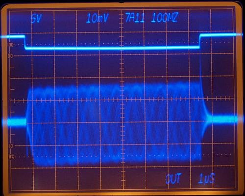
| 1mVpp sine-wave applied on
the bridge input. Scope triggers with the pulsgenerator, sine wave is
free-running from a noisy source. Camera opens the aperture for
many milliseconds. Brighter scope CRT intensisty shows an 80mV peak, higher than in the former xxxx photo. |
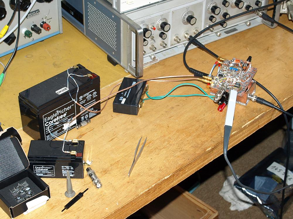
| Replacing the AC-Line Power Supply with three (12V and 6V) lead-acid battery results in - no improvement -
this seem not to be the problem, the spike looks always the same. |

| Every residue amplifier shows that slow rising sloop. It seems to
be from the settling time circuit. Approximately an unwanted 50µV
error. |

| Applying the same sine wave signal on different residue amplifer. (Vertical 250µV/DIV) The xxxx already limits the bandwidth, after switching the bridge OFF this amplifier can't follow fast. The xxxx does everything faster. Note: in the xxxx measurement, the oscilloscope amplifier is already overdriven, the rising OFF spike reaches about 150mV - the oscilloscope is about three times overdriven. |