First step
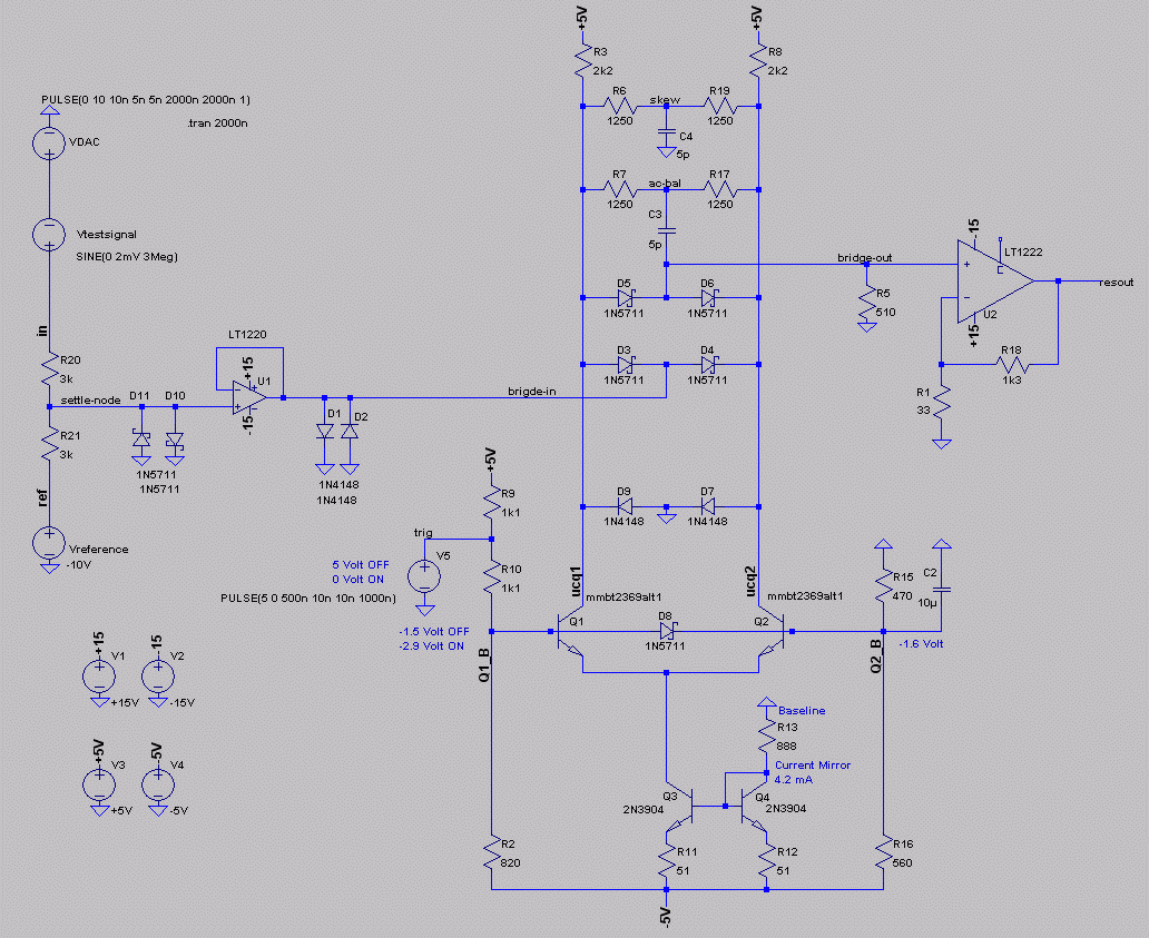
- redrawing the circuit, helped me to understand the function.
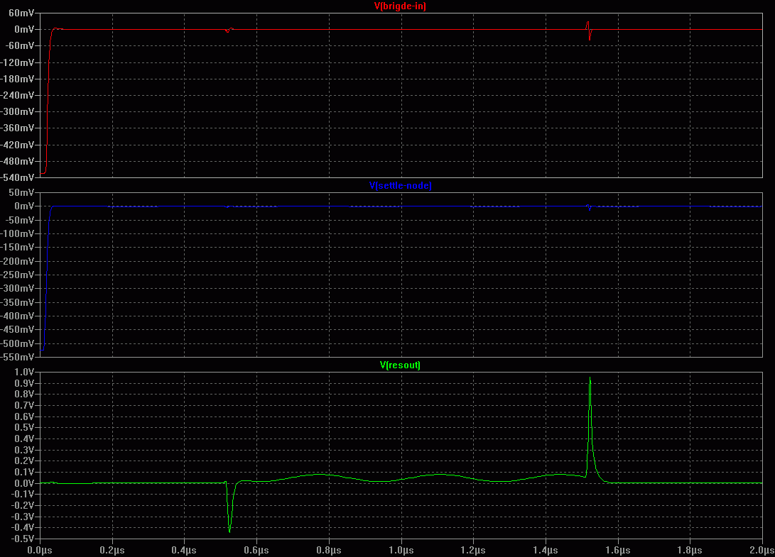
I tried to simulate the circuit, it was much more difficult than excepted.

- Diode bridge operates like a fast differential amplifier,
connected as
comparator. Base-Q2 has a constant DC voltage.
- Q1 switched byTrigger Puls ON
or OFF.
- After switching ON, diode network (D5, D6, D3, D4)
shifts "signal-bridge-in" to
"bridge-out".
- Diode network is placed between both
differential amplifier outputs.
- Current mirror Q3, Q4 set constant current.
- DC-baseline set amplifier current and offset.
- "Skew" and "AC -bal", amplifier frequency compensation
network for an equal switching between ON and OFF condition.
A tricky circuit. Scope photos in AN74 show only small switching
transients - almost unbelieveable. In the simulation I could not reach good adjustmensts for "AC-bal" and
"skew". |


