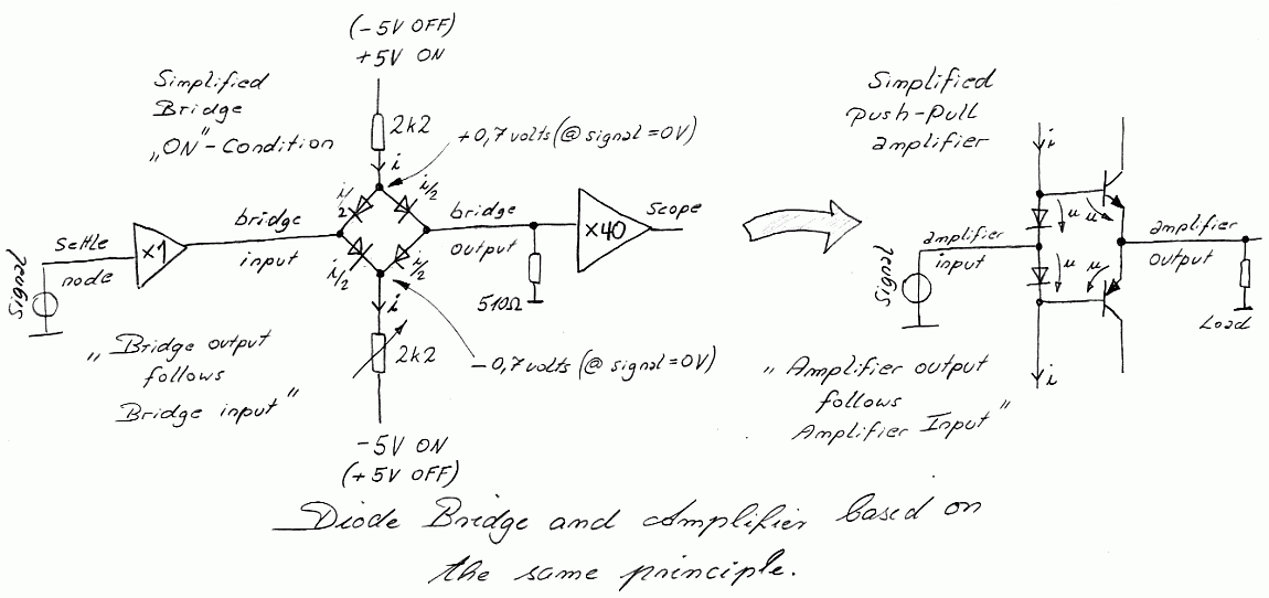
1. Function - Basic Principle


"ON-Condition" - Diode Bridge and Push Pull Amplifier - based on the same principle

They are almost the same, a Push-Pull amplifier and diode bridge sharing similar disadvantages:
  • A different junction voltage cause an DC offset in the output
  • Temperature coefficent of the ube and diode voltage approximately -1.9mV/°C.
  • Junction capacitances are a disadvantage for a good high speed performance
  • It is more easy to switch the junctions ON than OFF.


"OFF-Condition" Diode Bridge behaviours like an amplifier with a grounded input.
(note the reversed diode bridge)

Why using a diode bridge and not an integrated analog switch?

The analog switch has higher capacitances between input and output than a diode bridge network, this digital feedthrough will cause a transient peak during switching. The occuring parasitic transient peak will be amplified with a high Gain of 40 and therefore this switching peak should be low as possible.


A switched monolithic diode bridge network cause only less digital feedthrough in comparison with a standard switch.

This measurement circuit should not overdrive the oscilloscope with an amplified feedthrough peak, therefore it is a design target using lowest feedthrough elements. For example when using an integrated switch, the amplified feedthrough peak would highly overdrive the oscilloscope when observing the very small final signal settling. An highly overdriven oscilloscope amplifier trace take too much time to come back to its normal behaviour, most scope amplifiers are not specified under this condition, this is the reason why its better to avoid such a condition by the measurement circuit design from the beginning.


During "OFF" condition the scope measures:

  • output = Op-amp offset voltage * Gain 40
  • output = 510R Noise * Gain 40
  • output = Input Offset Current * 510R * Gain 40
  • output = DC Offset errors
  • output = noise
There is no signal coming from the settling node, the diodes are reversed and not conducting in a high impedance condition. The 510 ohm resistor hold the Gain 40 amplifier to ground potential.

Problems in the Switched Diode Bridge:

  • high diode capacitances (especial different capacitances of the diodes)
  • too low transistor transit frequency
  • transistor capacitance
  • different i vs. u diode curve characteristics
  • all four diodes should be exactly the same

Layout*** Problems with:

  • capacitance switch to ground
  • parasitic imbalance in capacitance and inductance
  • parasitic inductance in the wires of diodes and transistors
  • involving 16 Bit input signals, poor ground a big problem
  • involving fast transient currents (pulse generator), can destroy even a clean ground
  • radiation involved by fast transients near sensitive nodes
***(don't ever start with a classic layout - no chance - forget it)

Why clamping with a pair of schottky diodes?

Unfortunately a Schottky diode has a forward voltage of 300-400mV under approximately 3mA settle node current. An ideal diode with a extreme low forward would allow a better viewing without overdriving the oscilloscope.


Comparison of Different Diode Forward Voltages:
  • 700mV, general purpose diode
  • 400mV, standard Schottky diode
  • 200-300mV, special Schottky diode @25°C (e.g. www.avagotech.com)
  • 100-200mV, special Schottky diodes paralleled  @ >>75°C  ----- increased reverse currents.
  • 50mV tube diode ----- free radiated electrons from the glowing cathode, zero voltage current, heater problem.
  • 30mV high transconductane tube triode in diode connection ----- free radiated electrons from glowing cathode, zero voltage current, heater problem.
  • 20mV military microwave direct heated triode in diode connection ----- free radiated electrons from glowing cathode, zero voltage current, heater problem, crazy.
  • 40-80mV tube triode or pentode, switching grid to a negative pontential during low signal levels ----- heater problems, free radiated electrons elimated by switched grid.
  • low mV-Range,  bootstrapped diode clamping ----- amplifier problems with virtual grounds ----- need extreme good amplifiers.

DECREASED VOLTAGE - INCREASED PROBLEMS

There is no diode with a very low forward voltage.
I thought even about tunnel or backward diodes - nothing. 
Heating diodes cause much reverse currents.

Another idea is an easy controlable variable gain amplifier with excellent settling. I even thought about multipliers and Gilbert Cells.

No matter, first I try the diode bridge, getting experience.

- I am still a beginner in measuring settling time when writing chapter 1 -


back

www.amplifier.cd

Impressum und Haftungsausschluss