8.Trigger Generator Assembly
Describes the Trigger and Delay Generator.

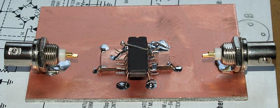
Building up the generator is an easy job compared to the diode bridge.
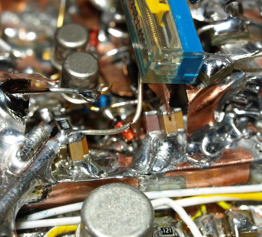
Soldered on the ground plane, between IC and ground plane an
intermediate +5V plane.
This construction makes soldering very easy and
all connections have a low inductance character.
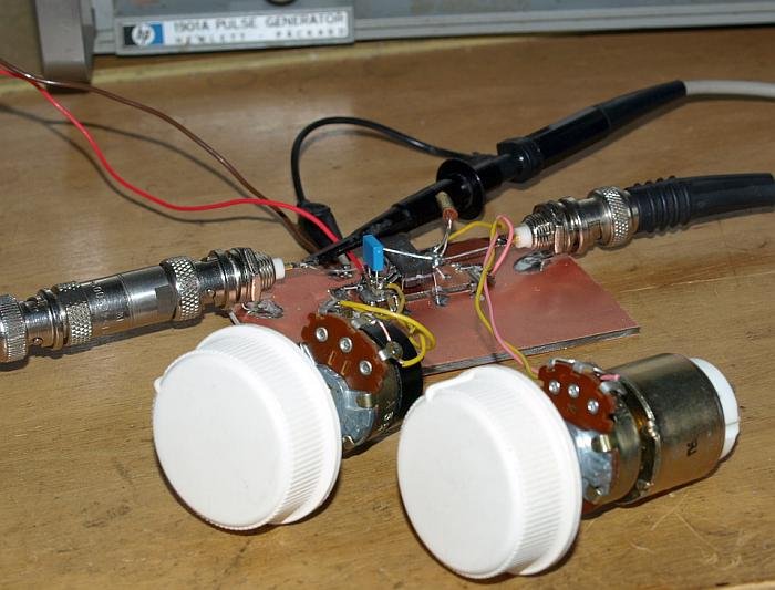
First test ciruit works, testing different RC values.
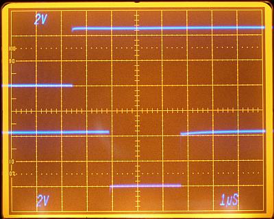
Long rising edge (7th. horizontal DIV) disappeared after full assembly.

Easy to build. Top and bottom ground plane used.


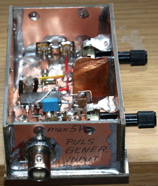

Middle - BNC for powering. Green power On-Off switch. Circuit can be supplied by a 6 volt lead acid battery.
Middle - Two diode in series (700mV+700mV) reduce 6.3 volt lead-acid battery voltage to a 5 volt level.
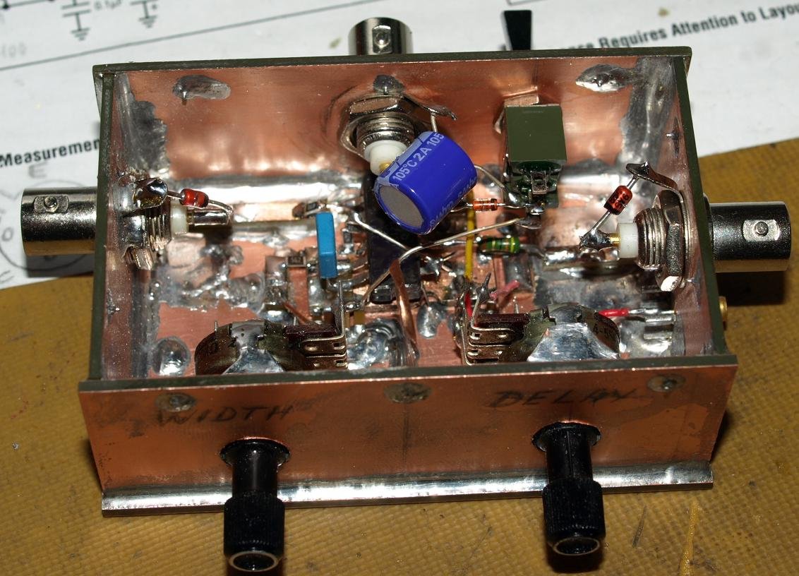
On all input and output an
5.6 volts zener diode - I'am scared when I adjust the pulsgenerator
output for a too high voltage by mistake.
Now it's also possible to supply the trigger circuit from a battery, I want to do that test.
Exact Middle - wire cut from Low Noise Voltage Regulator 5 volts supply and 1k1 resistor.
When supplying the 1.1k resistor with a battery from the trigger
generator cut the wire to the 5 volts from the xxxx.
It's only a test
for less transient loading of the xxxx.
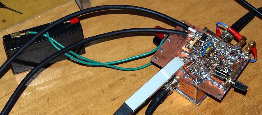
6 volt battery powered operation of the trigger generator.
Not a better results with battery operation observed.
back

Impressum
und Haftungsausschluss