Isolating transformer

The application note discuss a simple isolating transformer and measurement methods

Behind a isolating transformer stands a simple idea. This transformer affect in an galvanic isolation, for example to isolate an oscilloscope from the AC power line. Almost all scopes share the same common ground for all input channels. It's a difficulty to measure signals with different center of ground reference.

In many test equipment the circiut ground is also connected to the ground wire of the AC-line. Advantages that accrued are a higher safety in case of an electrical fault, on the other hand problems with measuring sensitive signals.

deutsch

Main handicap without isolating transformer: 

every electronics knows the 60 Hz buzz loops, generated by a galvanic coupling of circiut ground and the ground wire. Of course high frequency interferences using this path also. They are also transfered by the parasitic coupling capacities of power supply transformers.

These statements are principles of the classic school medicine for electronics. Frequently find - many developer are to pity to take care for a consequent consideration of these simple basics, or they are just too lazy to take care.

Always the same question, where to put the alligator crimp of the scope probe?

without the isolating transformer there is always the same problem, mostly without a clear answer. Where to connect the alligator crimp? Is it better to ground the scope by connecting the alligator crimp or by an alternatively way. Questions at questions, best answer in the majority of cases is trying. Unfortunately with every constellation there is another result. - buuh! it gives somebody a hard time, I want to measure and not a game.

Must it be like that? 

I've got my experience - clearly no! Why I'am feel so certain?

My way of affliction: learnded by school, "connect every device to the same AC socket, measure always on the same ground to prevent a short circiut - that's ok and correct. If you ever measure on signals with different ground, measure in this way: Channel A of the scope from high side to scope ground and channel B from low side to scope ground. Afterwards invert channel B and add both channels, result in a common mode rejected difference signal".

It's a simple like that?, with increasing frequencies the anyway bad common mode rejection of this pseudo differnce amplifier is to low, the amp shows nonsense.

An example: in particular with a digital scope the channel A-B methods works in some cases very poor. Consider just a 100mV AC voltage attached on a low frequency 70V voltage (common mode). Estimated 95% percent of all digital scopes use a 8 bit vertical resolution ADC. Assume your voltage per division switch shows 10V/div, it results in a maximum ADC range of 100 volts. (in reallity ADC range is even higher)

milkmaid calculation: 110 volts divided by 2exp+8 (256). One single bit of the ADC: 110 volt/256 = 0.4296 volt

Now I like to see how you want to show me this superimposed sine? Don't tell me: "there is only a stupid noise. I'am sure, I've measured it by using a new 25,000 dollar 1GS/s and 500MHz scope". I tell you, you've currently misused a nice 25k dollar scope. I'ts not your blame, many specialists and schools told you to do it in this way. I don't want to approach sombody to close -no- but I can't stay it any longer, how some people preaching a simple temporary solution to a standard.

measurement temporary solution: use the described two channel method only if the measured signal is high enough compared to the common mode signal. But who knows this before? This method is only advisable if the common mode signal isn't high frequency.

chaotic perilous temporary solution: the adhesive strip

good measurement solution: take a fast active difference probe with a high common mode rejection ratio of several hundred megahertz. Yes, exactly this thing the Tektronix sales representative adored for, but a decision maker never understand for what we need it.

good measurement solution for low budget: by an old Tektronix 7000 series scope together with a common used 7A26 dual channel amp plus time base. Look for the difference amplifier plug in's 7A13 and 7A22, many measurent problems can handled with them. A used P6046 FET difference probe it's also a nice probe for special purpose. Of course the actual Tek active probe series is superior by comparison, it's makes a lot of fun to measure with them, for example in fast digital circiuts or switching power supplies.

another good measurement solution: use isolating transformers, self constructed or industrial manufactored, also available at affordable low price on second hand markets or web auctions. Isolating transformers are suitable for measurements on sensitive signals. But there is a room for improvement, take a battery supply + additional difference amplifier. Then the only resultion path of coupling is the capacity of the circiut to the test equipment and back Even this can be reduced by a clever positioning. Somebody who handles often with extreme sensitive signals could give me surely some tips. I would be glad.

My measurements?

Very simple, I take to every device as a basic principle an isolating transformer. Sometimes I carry it to the extremes, I upgraded many of my equipment with accu power supplies, for example my low frequency spectrum analyzers, some meters and a accu power supply for a scope.

For many electronis sound this overacted, yes it's true - but why I always shall agonize where I should use a battery and where not? I just do it. I use my time and mind for the circiut, not for the way how to do it - it's uninteresting - so far the result were taken by a safe mesurement method.

In the meantime I collected seven isolating transformers and several battery packs. This method with a lot of isolating transformers needs also a lot of scopes - even these scopes a affordable at second hand markets. To have one or two top scopes -nice-, the following one can be of a lower qualitiy, depending on your budget and hunter and gatherer demands. So it's possible to get as many isolated channels you need. Also the maintenance of accus it's only a matter of a reasonable organisation.

With these work methods I made best positive experience. Buzz loops, dubious effects and ground connections, I remember it only from the past days or from the hearsay of others.

Outlook:

Build up of a active mini low frequncy difference probe by using modern instrumentation amps. Build up of a insulation transformer with special considerations about a minimum capacitive coupling.

ITrenntrafo.JPG (16948 Byte)

Trenntrafo_offen.JPG (18663 Byte)

simple self constructed designed insulating transformer. I got a meter in a original package box from 1954. The wood is kingly pear wood.

Two 250VA ringcore transformers, AC filters, safety fuses, overvoltage protection by varistors, monitoring for overheated cores and box.

Both transformers are identic and connected antiparallel. Secondary winding of transformer A ist connected to secondary winding of transformer B, resulting in a line voltage again on the isolated output. Take care that the transformers are safety protected and that it's allowed to use the transformers in this way. Use enough fuses and monitore the core and box temperature. It's dangerous for your life to work on AC line voltage, so please be careful and read also the Disclaimer Inform yourself about laws and technical directives about the use of such a device in your country.

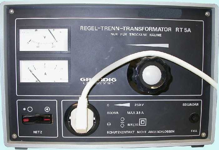
Example for a professionell isolating transformer Grundig RT5A

Isolating transformer Grundig RT 5A

Very reliable Grundig isolated transformer, unfortunately not any longer built. Power 800 VA and low internal resistance smaller 3.3 ohms, adjustable range secondarily 0 - 250V.


www.amplifier.cd

Contact and Disclaimer