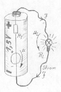
Static Output Resistance
A static
internal resistance meant, the resistance is constant for all load
conditions. This condition does not occur in nature, a dependence on
the load is always available, sometimes more, sometimes less. For many
voltage supplies, e.g. batteries may be spoken of a static internal
resistance, which remains constant in many operating points. With voltage
supplies, which are not regulated, a "static" internal resistance can be
defined
Dynamic Output Resistance and Amplifier
Here it
acts over an amplifier with negative feedback
Output resistance in the case of negative feedback under closed loop
conditions.
A
regulation is based on the principle of the negative feedback and a much
higher open loop gain than a closed loop gain. Also a Hifi amplifier has
an output resistance. Since a closed loop is present, I speak now of a
dynamic output resistance. Dynamically therefore, the amplifier tries to
regulate the output voltage, since it accomplishes continuously an actual
value with desired value comparison. In other words, an amplifier is a DC
source voltage with a very fast adjustable internal resistance. Since a
constant continuous (following the signal) dynamic adjustment of internal
resistance happens here, I call this internal resistance: dynamic internal
resistance in the respective operating point. The measurement of dynamic
internal resistance effected as in fig. 4 described, as signal source is
set an alternating voltage on the amplifier. Dynamic internal resistance
has validity for this operating point only.
In a
coordinate system output resistance is represented as y axis and as x axis
e.g. the pertinent operating point (e.g. the respective output voltage).
Still the first derivative could be formed by this function, in order to
meet further statements.
In electronics and audio world many names were found for output
resistance.
Damping Factor definition
In
principle all listed designations describe dynamic internal resistance in
the unit ohm. A privileged position assumes thereby the damping factor, it
into relation to loudspeaker impedance (4 ohms or 8 ohms) is set, the unit
shortens itself ohms. The damping factor corresponds therefore also to
output resistance, only in transformed way of writing.
 |
Fig. 5
shows the mathematical definition of the damping factor. Quotient of
attached loudspeaker impedance and output resistance in the
respective operating point of the hifi amplifier. The damping factor
is not a constant size, as it is often written. It stands in
dependence to variable internal resistance and loudspeaker
impedance. From technical view the indication of a damping factor is
meaningful only if the boundary conditions of the measurement are
indicated.
-
with which frequency
dynamic output resistance was measured.
-
with which amplitude
dynamic output resistance was measured
-
with which load impedance
dynamic output resistance was measured
|
|
It
would result in for example at all no sense, it would be even wrong
to determine a very good dynamic internal resistance during small
load and to calculate a quotient with 4 ohms, in order to receive a
good damping factor. Very meaningfully it is to be measured output
resistance with that load, for which also the damping factor is
indicated later. Without data of the boundary conditions the
indication of a damping factor from technical view is not
sufficient.
|
The
output resistance and the
open loop
of an amplifier depends essentially on the frequency, temperature and the
load. It lets general say, a very low dynamic output resistance is a good
condition for a low
distortion factor.
Dynamic output resistance depends to 100% on the open loop. If a dynamic
output resistance rises during very high load conditions, then the cause
lies in the fact that in this operating condition the open loop was
drastically reduced.
The
dynamic output resistance is a "regulatedoutput resistance" and can take
thereby very small values. Of course only validity for the range of the
still adjustable load. Thus it is clear why also a small operational
amplifier can have a small output resistance.
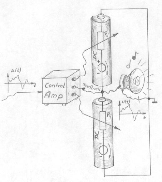 |
Fig. 6
shows a somewhat unusual model for further discussion for a common
used amplifier type.
To
see: two source voltages, with in each case an adjustable output
resistance. Now if a positive input signal applies against the
automatic controller (control Amp), then upper resistance is setted
to a very high impedance value, so that only very small current can
flow by the upper source. At the same time to it from the automatic
controller the lower resistance reduced to the desired current by
the loudspeaker flows so long. More exactly said, until the desired
voltage at the output adjusts itself. For negative voltages
conditions are changed.
The
feedback line is a part of constant control (regulation) whether two
resistances were setted also correctly. And the more precisely
control happens, the more highly is the open loop.
If
the desired voltage is zero V, then both resistances are adjusted to
the same value during same source voltage. However to which value?
Good question - until the desired idle current of the output stage
is reached.
The
transistors in the amplifier takes over the role of adjustable
internal resistances.
|
Large amplifiers small output resistance? - small amplifier large output
resistance?
A large
hifi amplifier - that means not that dynamic internal resistance is
automatically very small. No, a very well made small amplifier can be
quite better than a less well developed large amplifier. The substantial
difference is: the small amplifier cannot follow with rising load any
longer, its dynamic output resistance rises strongly. While with the large
one only with larger load dynamic output resistance rises somewhat.
Effects on a bad amping factor
Keep in
mind, an indication of a damping factor is technically only meaningfully
under indication boundary condition only if for the DUT's the damping
factors are present, which were measured under similar boundary
conditions, then becomes a number comparison possible. Effects on bad
damping factor are, the output signal correspond less to the input signal.
The effects are
linear and
also
nonlinear distortions.
Also a
loudspeaker can generate voltages. An amplifier with low dynamic output
resistance can compensate these disturbances better than one with a high
damping factor. Loudspeakers generate inadvertent voltages to their
connectors, similarly like the function mode of a microphone. The
amplifier must reject these. A measure for it like generated disturbances
being suppressed, is e.g. the load Rejection Ratio. Damping factors affect
the sound, loudspeaker manufacturer have thereby experience.
A
relatively linear controlled system reduces also the effect of the
generation of nonlinear distortions. With which we concerned at the open
loop amplifier without feedback. An open loop amplifier meant, the
amplifier does not have an overall negativefeedback of the output signal.
Only individual amplifier stages using negative feedback, e.g. through
emitter resistances or through cathode resistances with a tube amplifier.
A
feedback free amplifier works in a steered mode and not as regulation.
During directly comparable achievement of both amplifiers types, the
steered type has a higher output resistance than the regulated amplifier.
The developer of a steered only amplifier directs his special attention to
linearize his circuit. This method helps to keep distortions low.
|