Distortion of a Forest and Meadows Audio Amplifier


Before you read this report, have a look at Measurement System Amplitude Response for Audio Amplifier within this report I explain the used measurement system. Interesting also the report What are Open Loop, Slew Rate and Bandwidth? The report demonstrate the close relationship of Open Loop, Amplitude Response and Distortion. A mathematical model supplied with measurement values.

Open loop and Distortion:

I wrote it sometimes, to reach low distortion it's a force having a high open loop gain and a linear control path. To measure the linearity of a control path, that's difficult, in particular if you don't know the wished frequency and you can't open the amplifier loop. Discussing the open loop is more easy. The amplitude response let you realize, that with an increasing load the output voltage decreases. This effect caused by the dynamic output resistance. A high open loop leds to a low output resistance.


power_unsym.gif (22263 Byte)

in_out_voltage.gif (22369 Byte)

gain_volt.gif (21963 Byte)

Figure 1: adjusted output power

Figure 2&3: adjusted input voltages and the resulting output voltages

Figure 4&5: left picture shows the Gain vs. Input Voltage. Right figure Gain as Polynominal Fit Funktion

The amplitude measurement system measured 60 different output power conditions with 4 ohm load Starting at maximum output power (1V below clipping, 15.7 Vrms). Volume control at 70%. To set the system first measured frequency was 200 Hz, in the next step the measured frequency of 300 Hz. Lowest Output power was 60mW.

Input and output voltage. Vin max 306mVrms, Vinmin 10mVrms. Voutmax 15.7 Vrms, Voutmin 0.5 Vrms. The 60 steps should be enough to measure the whole power dynamic of the amplifier. The measurement range of both voltmeters remain unchanged.

This voltmeter can measure only positive true rms values, for negative voltages the positives were mirrored on the y-axis. In reality this would be an amplifier with the same behavior of the negative and the positive half cycle, with xactly the same open loop. That's not realistic but ok for this model. The right figure does a 9th.order polynominal fit of the measurement values.

Figure 5 similar to the measured values in Figure 4. I did the polynom  to 9th. order, this should be enough.

copyrights at Ralf Ohmberger


Input signal is ideal mathematical sine

This ideal sine will be multiplied with the polynominal fit function. The applied amplitude was 300mVp.

The frequency of the sine in the model is 300 Hz. We remember the report Amplitude Response of the forest and meadows amplifier, at 300-350 Hz this amplifier has a gain maximum. For this frequency follows now the measurement and simulation.

ideale mathematische Eingangsspannung

Figure 6: shows the applied mathematical sine

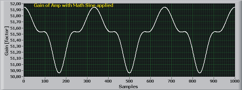
Modulierter Gain

Figure 7: shows the modulation of the nonlinear gain by the applied sine. With an ideal amplifier this would be a straight line.

Ausgangsspannung am Verstärker

Figure 8: shows output voltage generated by the amplifier modell, of course in the time domain looks like a sine.


Note: in Figure 7 and 8 a small optical mistake happens. Figure 7 shows 1000 samples and Figure 8 shows 2000 samples, both axes should have 2000 samples.

Now, please take a look at the samples "zero" in Figure 7&8, no output voltage leads to no current and a maximal open loop resulting in a maximum closed loop gain of 51.95. When the sine in Figure 8 reaches his positive maximum at sample "167", the gain in Figure 7 decrease to a minimum of 50.8, because the maximum output current reduces the open loop and therefore also the gain. Mathematical description in What are Open Loop, Slew Rate and Bandwidth?

The whole procedure of the modulated open loop repeats permanently in action with the polynominal fit function in Figure 5.

This is one reason how distortion occurs. A nonlinearity of the control path.


The FFT makes it interesting now

we check first the ideal input sine. After that the modulated output voltage of the output.


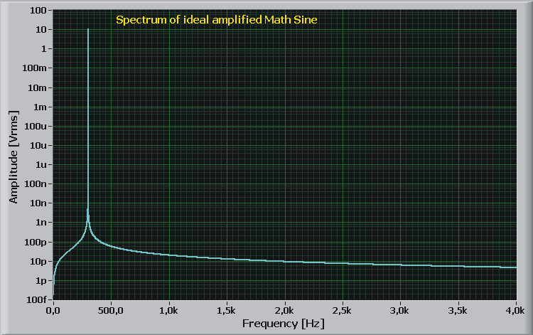
Spektrum des idealen Sinus verstärkt mit idealem Verstärker

Figure 9: shows the FFT of the ideal sine amplified with an ideal amplifier. Would be nice this could be reality - 220dB signal to noise and distortion free, where can I buy it?

Some general notes to the Fast Fourier Transformation: in this case I calculted without any leakage filter (Hamming, Blackma... etc) also good results, why? I used 600 complete periods of a sine wave. The data block stops at zero crossing and starts also at zero crossing point. The FFT puts one block after the old block and so on. Important is the block stops exactly on the same point in the period where it has started. If it's possible to do so, you don't need a window function.


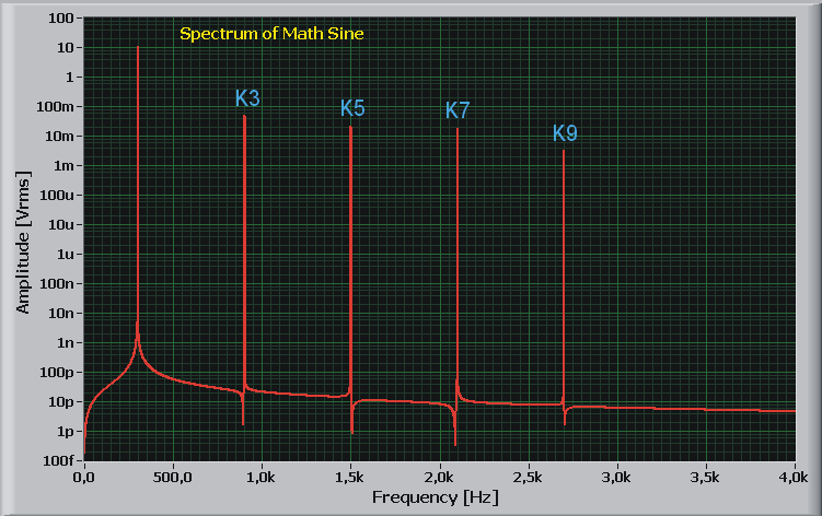
Spektrum des Verstärker Modells mit symetrischer Open Loop

Figure 10: shows the output voltage on the simulated fitted amplifier. The ideal sine calculated together with the exactly mirrored polynominal fit fuction.

What's interesting here?

The spectrum has only odd numbered harmonics, where are all the even numbered harmonics?

Even numbered harmonics can't generated by an amplifier, amplifying the positive half cycle exactly the same as the negative half cycle.


for the odd harmonics:

1*1*1 = 1 or -1 * -1 * -1 = -1 

the sign remains with odd numbered on the output always the same as on the input.

for the even harmonics: 

1*1 = 1 oder -1 * -1 = 1  

the sign of the output is always positive.

That's simple mathematic.


How to get the even numbered harmonics?

Now let me disturbe the exactly mirrored polynominal gain fit function a little bit, like in real systems.
How to do?
I mirror the gain function from positve half cycle to the negative not with exactly -1.00, no I do it with -1.01.
So I add an error 1% unsymetrie. Back to the even numbered harmonics, let's have a look for the influence of only 1% unsymetrical gain.

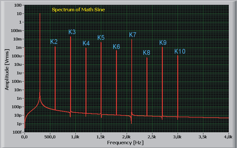
Spektrum des Verstärker Modells mit unsymetrischer Open Loop

Figure 11: shows the output voltage on the simulated fitted amplifier. The ideal mathematical sine was multiplied with the 1% error mirroded polynominal fit function.

What's up now? here are the even numbered harmonics!

Only this 1% is enough to generate some even numbered harmonics.

Amplifier and the results of this calculation?

I describe two common used amplifier types.

Class A as unsymetrical single supply amplifier

It is often said this unsymetrically designed type of amplifier having a more smooth soft sound than a symetrically designed amplifier. Many times it is a tube amplifier. Why we find a tube amplifier often with unsymetrical designed circiut? Main reason is tubes are only available in "NPN" versions. (Sorry for these terrible word "NPN" together with tubes). I don't know "PNP" tubes. Having only NPN technolgy it's more easy to design a unsymetrical amplifier than a symetrically designed one.
Unsymetrically amplifiers comes in many cases also with a unsymetrically Open Loop for the positive and the neagative half cycle. This is sometimes easy to see on an oscilloscope, if you drive the amplifier in condition with enough distortion you see them also on the scope. Seen as "round egg" the negative half cycle is round, the positive more pointed. You remember? The reasons for this behaviour were described in this report. With an transistor amplifier it's the same as with tubes. Ok, the tube having general some more "natural" curve characteristics than a transistor. Again: with a transitor amplifier it's also possible to reach the smooth sounding "egg curve", no problem.

Class A or A/B als symetrically designed amplifier

now comes the many times called "Bad Boy"  a transistor amplifier. This is not true! It's called having a cristall clear more hard sound, not so smooth as with tubes. It's true, but the reason in many cases is the "circiut design" not the type of part itself! To say something in detail, you also must also check the used circiut in detail, before doing a statement. Would it be possible to reach an exactly mirrored open loop gain, even numbered harmonis would be canceled out. But in reality this not possible, nobody can find transistors with exactly the same gain behaviour over temperature, current, voltage and frequency. It's possible to design a symetrically amplifier with a high open loop. If you get this amplifier stable, you'll get a fine amplifier. But the difficulties are: reaching a high open loop gain also for high frequencies and stable! This type of amplifier doesn't have many times the "egg curve"

Now the real measurements

The following are the distortion plots of the forest and meadows amplifier.

14Vpeak300Hz70per.gif (74824 Byte)

14Vpeak1kHz70per.gif (68347 Byte)

1400mVpeak5kHz70per.gif (64581 Byte)

Figure 12: shows the spectrum with full output power under a 4 ohm load. Vout reaches 20.58Vpeak with 300Hz. The volume control is adjusted to 70%. Resulting output power 53Wrms. Easy to see the firework of harmonics, power supply harmonics and many mixing products. Total harmonic distortion 0.35%. Total harmonic distortion plus noise 0.64%. Figure 13: shows the spektrum with 2/3 output power. Load 4 ohm, vout 14.1Vp and 1kHz. Volume control at 70%. Output power about 25Wrms. Esay to see the bad power supply (distortion seen are the sum of source and amplifier) Total Harmonic Distortion 0.077%. Total Harmonic Distortion with noise 0.561%. Figure 14: shows the spectrum with a low output power on 4 ohms, Vout 1.41Vp and 5kHz. Volume control at 70%. Pout 250mWrms. Bad power supply+source reaching now a Total Harmonic Distortion of 0.043%. Total Harmonic Distortion plus noise 1.75%. Remarkable the tone at 19 kHz, more about it later..

100mVpeak1kHz70per.gif (72300 Byte)

100mVpeak5kHz70per.gif (65018 Byte)

quelle1kHz750mVrms.gif (67283 Byte)

Figure 15: shows the spectrum with a low output power. Load 4 ohm at Vout 140mVp and 1kHz. Volume control at 70%. Vout 25mWrms. Sorry in this measurement I scaled the vertical amplitude wrong by a factor of ten. The 140mVp are true. Total Harmonic Distortion 0.02%. Total Harmonic Distortion + Noise 7%.

Figure 16: shows the spectrum at low output power. Load 4 ohm, Vout 140mVp and 5kHz. VOlume control 70%. Pout 25mWrms. Again wrong scaled by factor ten, the 140mVp are true. Total Harmonic Distortion 0.034%. Total Harmonic Distortion + N 7%.

Figure 17: shows the spectrum of the signal source at 1kHz and 750mVrms. Total Harmonic Distortion 0.00071%. Total Harmonic Distortion + N 0,78%. The source is not very clean in the power supply. I should replace the supply by a self designed.

50ohm_an_amp_input_fullvolume_mit_Radio.gif (61906 Byte)

50ohm_an_amp_input_fullvolume_ohne_Radio.gif (55715 Byte)

50ohm_an_amp_input_fullvolume_netz.gif (70582 Byte)

Figure 18: shows the spectrum of the amplifier alone. The input of the amplifier is terminated by 50 ohm. Volume control at full range. High power supply distortion even without output voltage and any output current. The 19kHz tone is still present. Figure 19: shows the spectrum of the amplifier alone. Conditions as in Figure 18. The 19kHz tone? only present if the radie band switch selects FM, with AM the tone disappears. Nice to see the mixing products of the 50Hz AC with the 19kHz. The 19kHz are interference with the FM stereo decoder. Figure 20: shows the spectrum of the amplifier alone. Same conditions as in Figure 18. A closer look at power supply harmonics. These unloaded power supply leaves no wish open for many power supply harmonics. Bad.

Which other measurements could be done?

Yes, you could plot the distortion and the harmonics as a function vs. frequency. The load could be an additional parameter. But this needs an automatic measurement system (it's currently under construction). But really there is no need with this amplifier to do it. The amplifier behavioure as expected, with an increasing load the distortion increase also. With a lowest loads the distortion also increase. The questions are only how much are the distortion and at which levels and loads they appears.

Also the unregulated power supply gives me not much satisfaction. What you see as power supply distortion, I can hear it already a little. That these amplifier will be not a superstar in the discipline Intermodulations Distortion, easy to guess. No need to measure it.

Many of the results could be predicted from the bad amplitude response.

Summary

As expected for a forest and meadows amplifier. Not bad harmonic distortion levels for a medium power, bad for harmonic distortions + Noise. I'am dissapointed from the power supply, no wonder a good passive or active power supply needs parts, and parts costs money for the manufactorer and customer. Also interested the interference by the FM stereo decoder.

I will use this amplifier for more measurements, may be one times I'll stress him so much that he'll tell me good buy. Rest in peace.


www.amplifier.cd

 amplifier     contact and disclaimer