|
Again I did many experiments for some hours to find the right parts and
another compensation method, after these experiments I was sure that I'am able to
compensate every tested opamp for a flat response under bipolar and
unipolar configuration. |

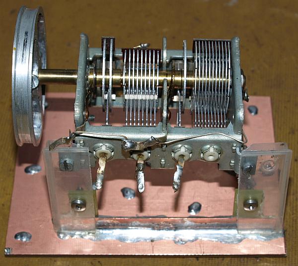
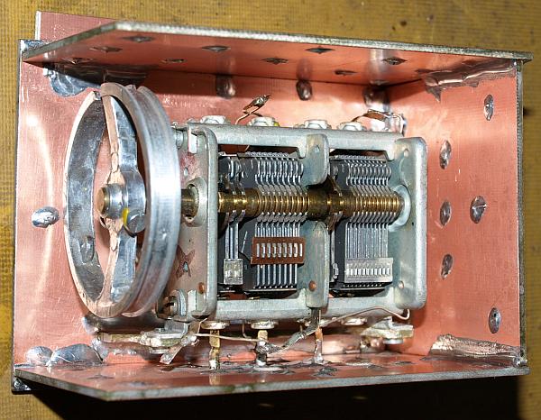
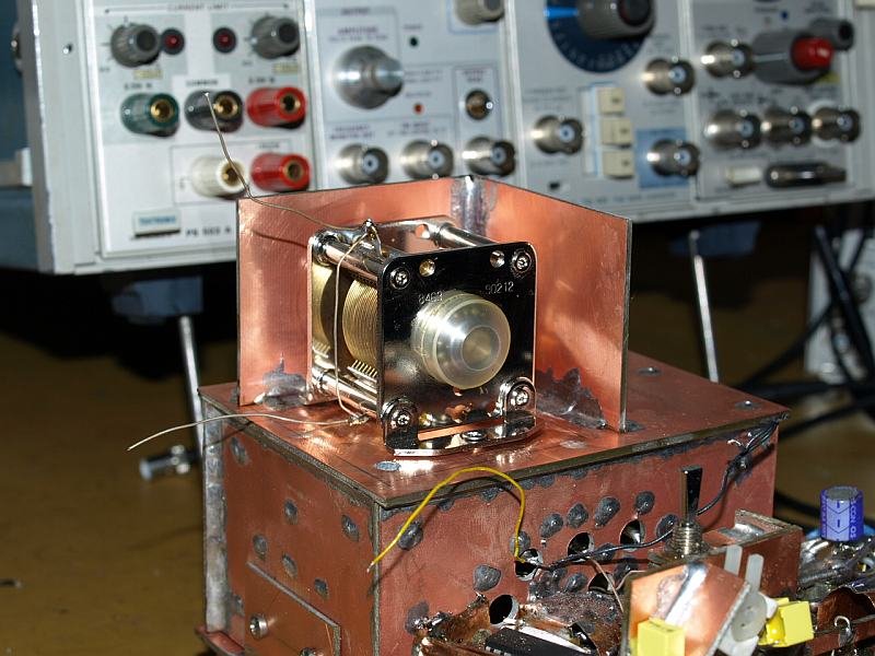
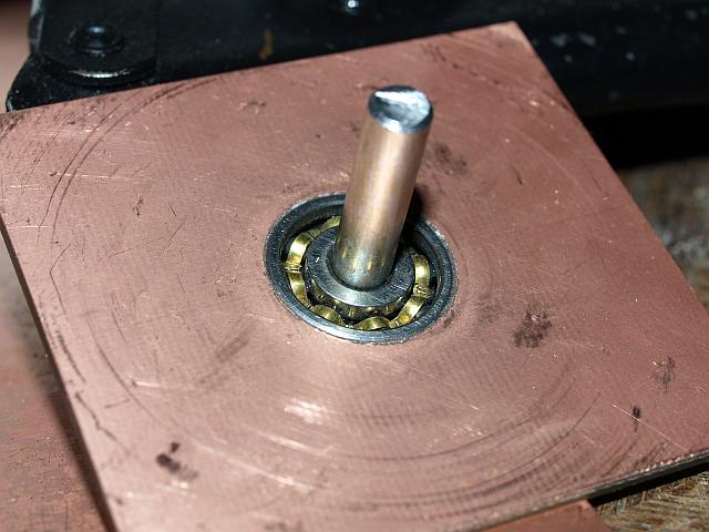
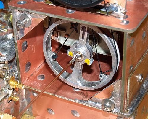
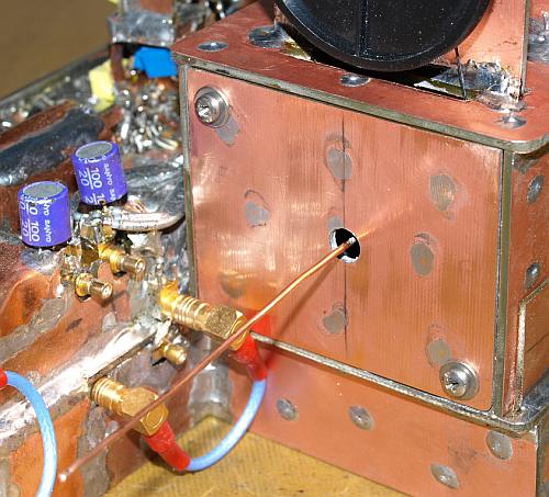
| Mounting the air-capacitor on a copper PCB. The small carrier epoxy PCB made with small dimensions. Capacitor body has rotor potential. |

| Amplifier xxxx with DAC xxxx for a 0V to -10V Full Scale Step Unfortunately the response is no more flat, remember before the
capacitor was hanging on air wires only and the response was more flat. |

|
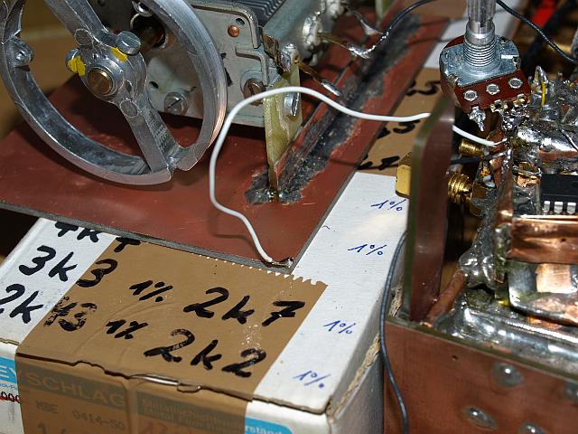
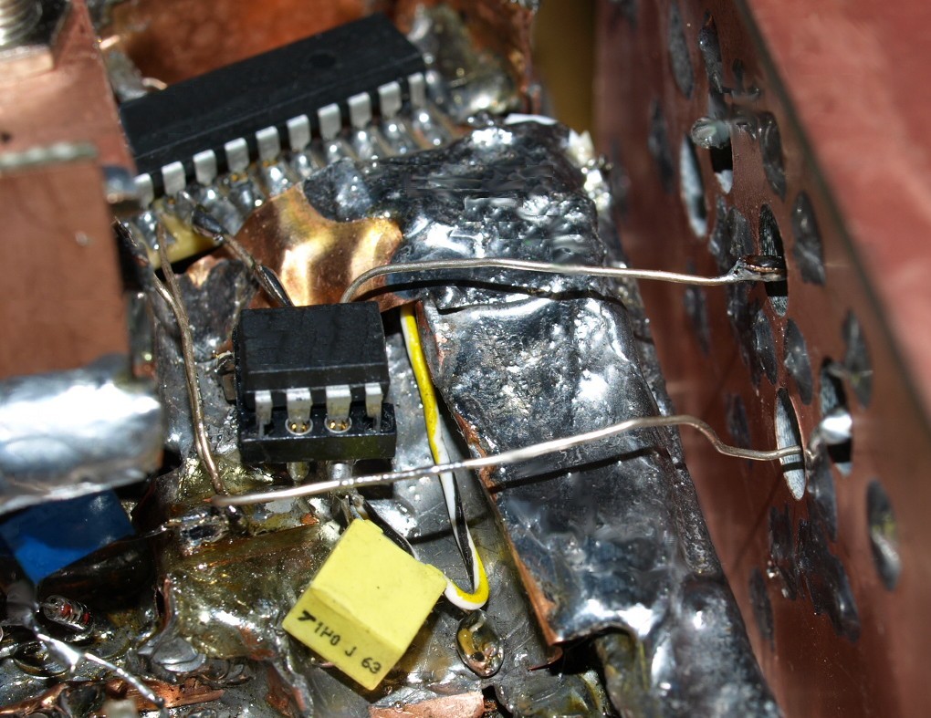
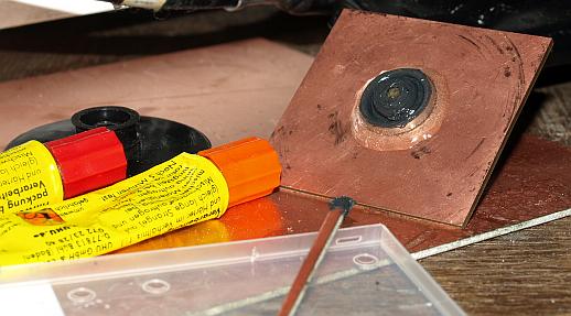
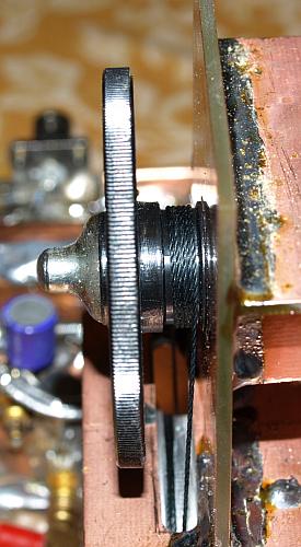
Bipolar Output Compensation required in my assembly a second capacitor for a very flat response. This is a full metal,
new old stock VALVO capacitor in highest air
capacitor quality. Made for the German military, had the
typical long part numbers on the packaging. |


|
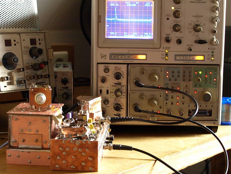
Measurement Action - today using the 7D20
digital oscilloscope Plug-In with an averaging capability. Left there
are two 500 series Plug-In's in a power supply compartment, it's a TG501 Time Mark Generator and a PG506 Calibration Generator, I used them before to calibrate the 7D20 horizontal and vertical gain in the used 7904 mainframe. |

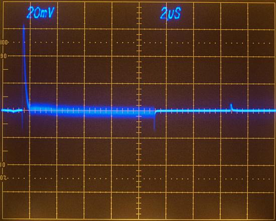
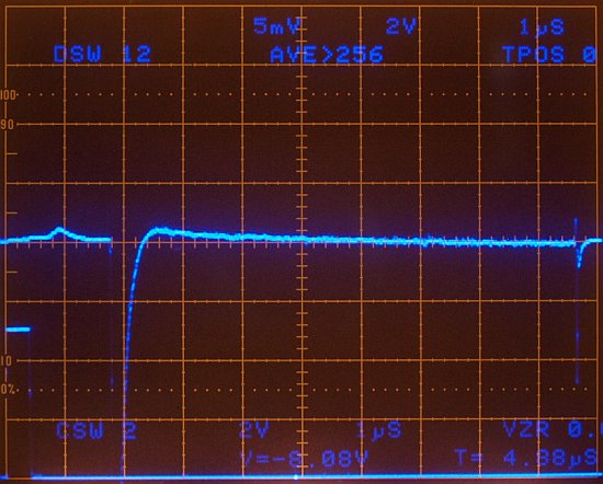
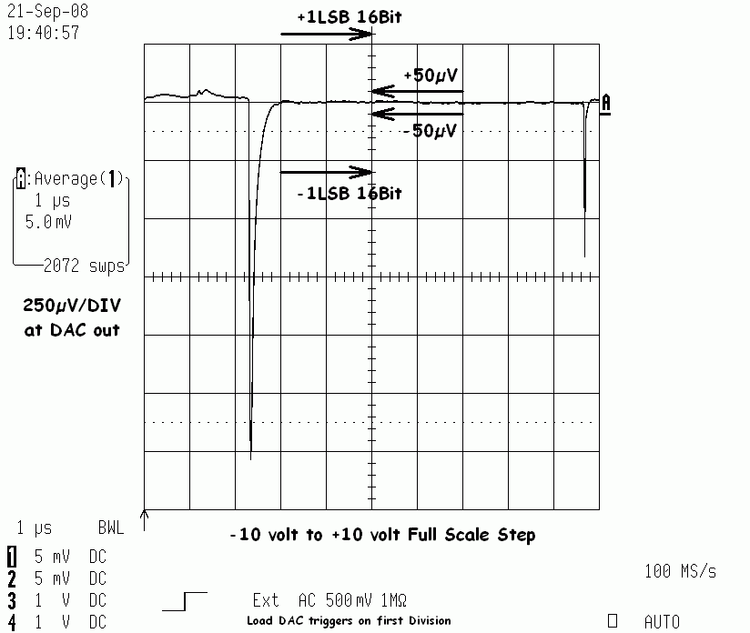
| Amplifier xxxx with DAC
xxxx for a 0V to -10 Volt Full Scale Step. Note, the oscilloscope
vertical gain set for 5mV/DIV (similar to
125µV/DIV at the Settle-Node and 250µV/DIV at the OP
Output).
1 LSB = 152µV
Measurement Bandwidth approx. 10 to 15 MHz. Displayed Noise approx. 350µV peak Lower Trace, time corrected LDAC signal (2V/DIV) |
|
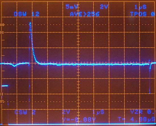
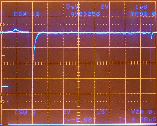
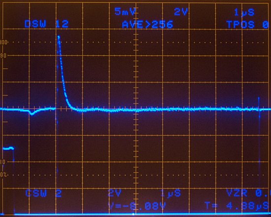
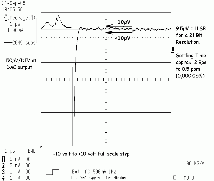
Same measurement as above, but the 7D20 Plug-In operates in it's averaging mode - 256 samples averaged
250µV/DIV (Op Output) - 152µV (1LSB)
Averaging reduce unwanted nonperiodic noise signals, only periodical signals remaining. The double capacitor compensation is very flat adjusted, it can be said after 2.6µs the DAC reaches a stable tolerance band of 1/5 Division (50µV). 2.6µs Settling Time to 5ppm (approx. 18 Bit) for an aperiodic adjusted falling 0V to -10V full scale step.
Such a flat precision compensation takes about 15
minutes adjustment.
|

|
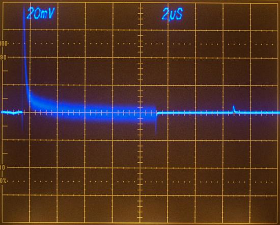
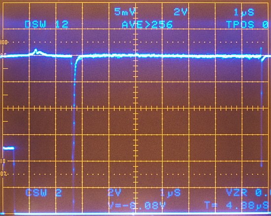
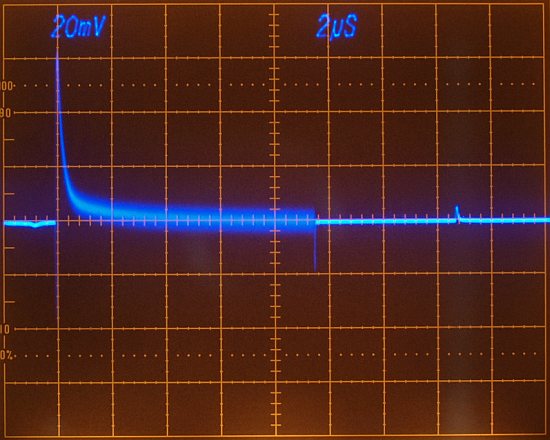
If you think in the 5mV/DIV the small overshooting looked dramatically,
have a look in the 20mV/DIV view without averaging - here it looks
almost flat - remember the 20mV/DIV setting was OK for an 16 Bit
adjustment and we are talking about an 16 Bit device and not about an
18 Bit device, anyway we will recompensate for the 18 Bit now: |
|
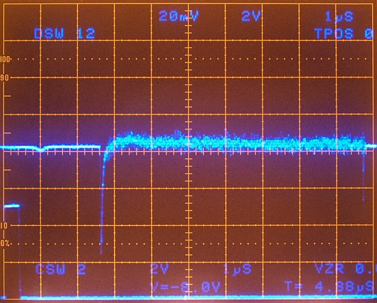
The only thing sombody could complain, there is a small 20µV
ringing between division 3 and 5 (approximately 1.25 MHz). I will do a
future trial to remove it. |
| In many of my scope photos the compensation is always flat, that's because I give my best for a good adjustment. When seeing always a flat compensation may be the reader guess "it is easy to do flat compensation" - no it's not - I want to show in one example how critical the adjustment for a flat compensation really is. After some hours of doing experiments, this work changed to a "compensation-sport". |


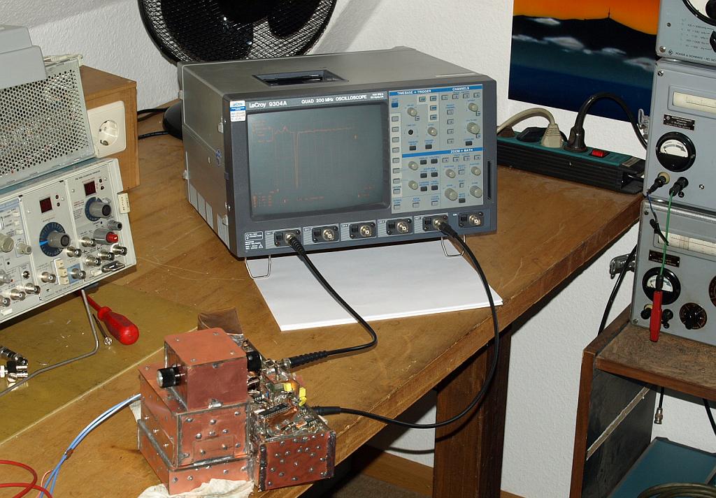
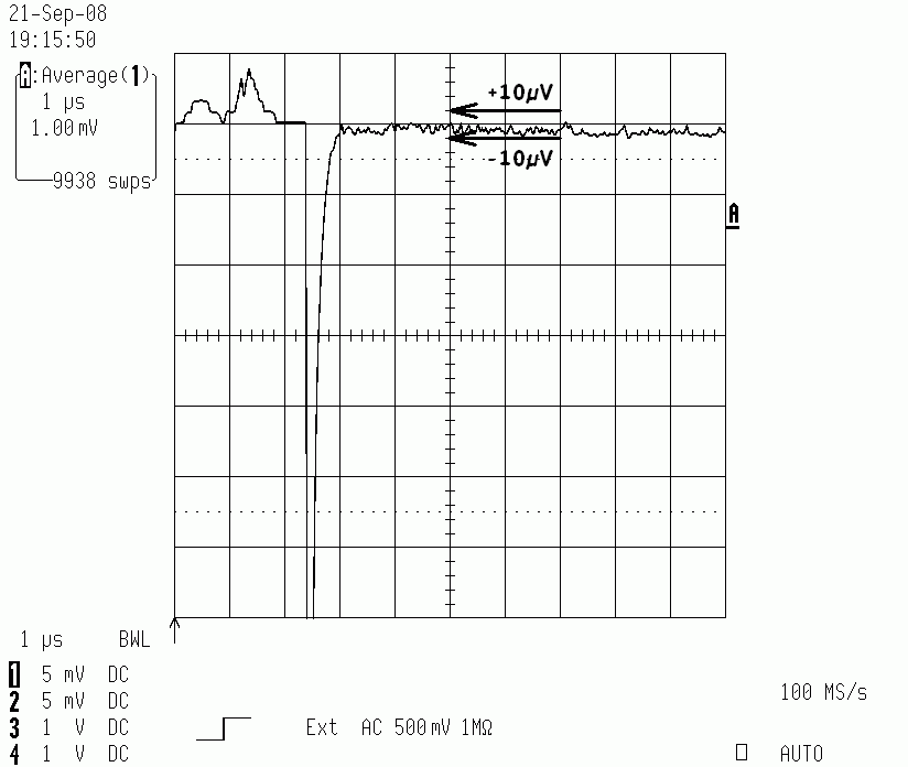
| Using a LeCroy 9304A Quad 200 MHz Oscilloscope in it's math averaging
mode under a limited 30 MHz bandwidth. The 9304A can do near infinite
averaging, the old 7D20 plug-in reaches the limit after 256 sweeps. The following compensation is very flat and took me almost one half an hour to adjust. Such small voltages buried within the noise getting hard to observe. Every little change on the compensation take time to wait for at least 50 to 100 samples to see a new change. Also the offset bias needs many times a readjustment. |
|
| The oscilloscope
amplifier is not overdriven under the used 5mV/DIV
vertical amplifier gain (additional expanded by internal math to
1mV/Div), because the vertical amplifier sees 5mV/Div. Measurements of
such small levels are many times questionable. I
can tell you, reaching a flat response under a high gain, it's really a
hard job to do. Again, it took me 30 minutes playing with the
compensation settings. Try to reach the same results using the "paper development" methods nowadays - haha.
|
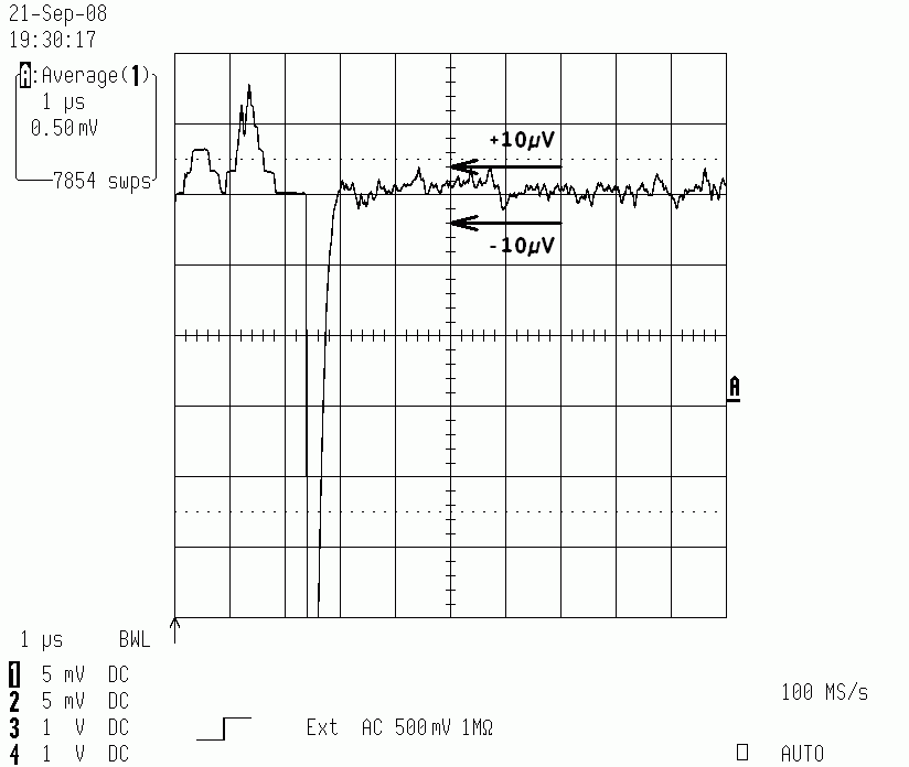
| Same measurement as the last one, averaging
increased to 9938 sweeps - no further improvement compared to 2049
sweeps. Increasing the average makes no further sense, the averaging
stability limit has
already reached. |
Aperiodic settled waveform, measurement with a 5mV/DIV
deflection factor, corrosponding to 250µV/DIV on the DAC output.
|


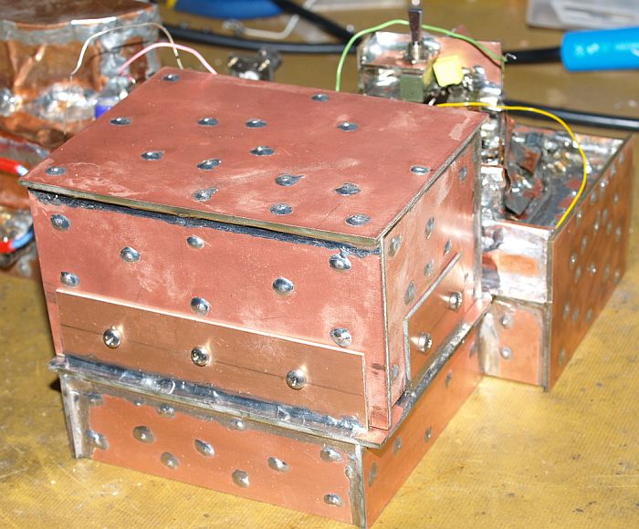
| Now the instrument looks very different compared to the beginning
- that's a brute force development method what I am doing
here in this project. Keep your mind free ----- Do only what's technically necessary ----- Don't care for the technical rules of people who can't help you in the project. ----- With the development methods common used nowadys you would measure the Settling Time with luck for a 14 Bit accuracy but never succesfully for up to 20 Bit vertical resolution. |