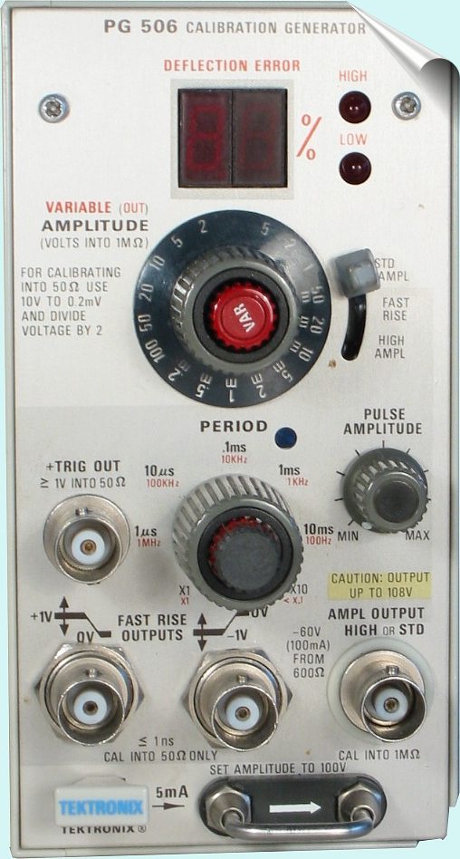
Der PG506 ist ein Rechteck
Generator der zur Amplituden Kalibrierung der TEK Scope's Geräte genutzt
wird. Die Höhe der Amplitude ist extrem genau, Ausgänge für schnelle
Flanken <1ns werden auch geboten um Überschwingen bei den Scopes
wegzutrimmen.
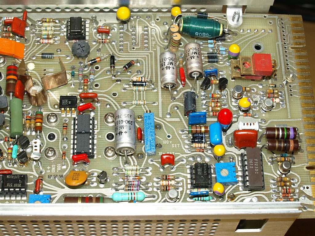
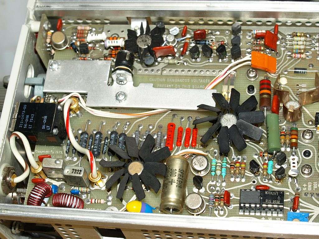
Unter dem rechtenTransistor mit Sternkühlkörper sitzen die beiden
getauschten Dioden (siehe Text weiter unten). Both changed diodes under
the most right transistor with the black heatsink (see coming text).
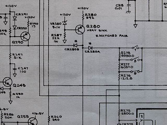
Das Gerät hatte einen Fehler, die
selektierte * Diode CR280A war defekt, das hat mich ein paar Stunden
gekostet, man sucht meist wo anders. Der Ausschnitt aus Schaltplan
zeigt den internen 100 DC Volt Standard, aus dem alle
Kalibrationsspannungen abgeleitet werden. Durch die defekte Diode war
die Urspannung anstatt 100 Volt ca. 120 Volt. Die beiden Dioden
sind werksselektiert, wahrscheinlich auf gleich Junction Spannung bei
einem bestimmten Strom um einen Gleichlauf zu garantieren. Ich habe
daher beide gegen zwei 1N4811 vom Gurtabschnitt getauscht. Zuvor wurden
an einer
Stromquelle
zwei Stück auf gleich Spannung selektiert. Die Dioden sind auch auf der
Leiterplatte direkt nebeneinander montiert um eine ähnliche Temperatur
zu erreichen.
Nun läuft das Gerät wieder wunderbar, es ist
eine Freude damit ein Oszilloskop einzustellen, gerade wenn man viel
die 7000er Serie benutzt muss man doch manchmal beim Tauschen der
Einschübe entweder die Verstärkung oder die Zeitablenkung korrigieren,
da ist es eine wunderbare Sache, wenn gleich immer ein PG506 daneben
steht, der etwas genauer ist als die im Oszilloskop eingebauten
Schnellkalibratoren. Kaputt ist jetzt lediglich nur ein einzelnes
Segment aus der LED Prozent Anzeige, dieses zu tauschen ist nicht
einfach, man muss hierfür die ganze Frontplatte auseinanderbauen, zum
Glück habe ich das Ersatzteil nicht.
The
instrument had a fault. The * selected diode CR280A was defect. This
schematic ist part of the 100 volts standard amplitude, 120 volts
applied nominal on the emitter of Q280, with the faulty diode the
nominal 100 volts node showed almost 120 volt. After some hours I
located the fault. These diodes are factory selected for a similar u
vs. i characteristic and on the board they are mounted close together
for a similar junction temperature. I replaced both of them with two
1N4148, I took two diodes from a reel and selected two of them using a current calibrator,
I choosed two diodes with the same voltage. Now the instrument works
wonderful again - but one LED segment from the percent indicator don't
lit, changing the seven segment display seems to be a hard work, every
knob must removed and the board removed from the front-panel, I'am
lucky having not the spare part.
 Here are some photos of the fast rise outputs:
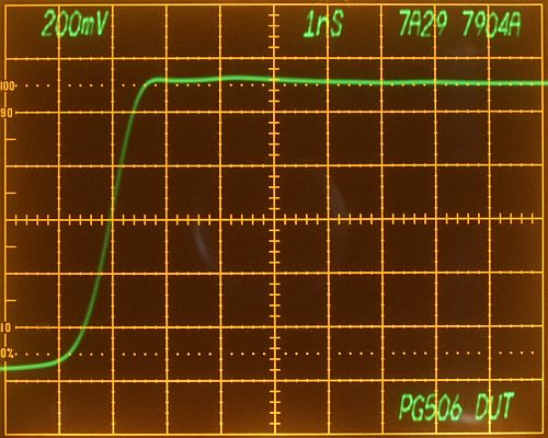
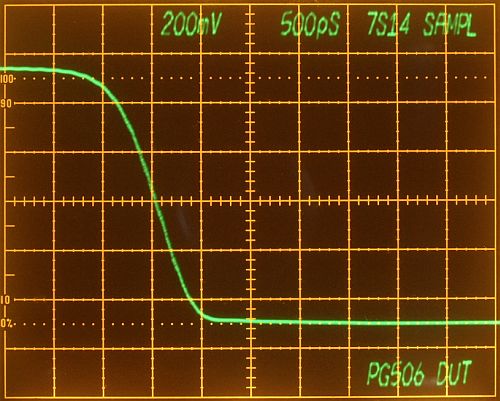
Fast Rise Output:
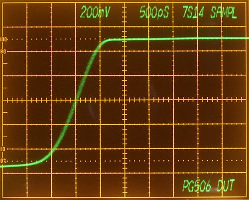
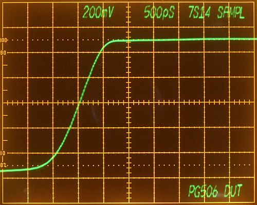
Fast Rise Output PG506 with
7S14 Sampler (1 GHz tr<=350ps) in a
7904A mainframe
Right photo: Sampler switched in Low Noise position, left photo: switched in normal position
All instruments are excellent,
the PG506 has a fast and very flat step response without overshooting.
This is an ideal source for a vertical amplifier frequency compensation
adjustment. The sampler works perfect for such repetetive signals, the
7S14 shows no overshooting. A sampler is a powerful instrument, I
don't want to miss it.
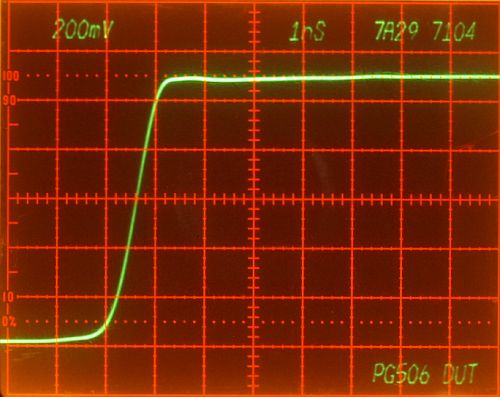
Fast Rise Output PG506 with a
7A29 amplifier (1 GHz) in
7904A and
7104 mainframe
These are the results with a real
time amplifer. The 7A29 with it's 1 GHz bandwidth is the fastes
amplifier Plug-in of the 7xxx series. The 7A29 has also a very flat
response, almost the same flatness as a sampling system - what a
wonderful amplifer Plug-in. Also both mainframe showing the same
risetime, it seems the 7904A vertical amplifier has more
bandwidth then specified, I read somewhere the verticals in both are
very similar, when I see these results I can believe. The 7104 Micro
Channel Plate CRT has a very sharp focus, compare for example the
figure "7".
Direct Comparison of Real Time Amplifier and Sampler
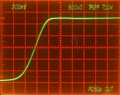
Results of two different measurement systems - Real Time vs.
Sampler. Both systems showing almost the same flat response and exactly
the same risetime.
- Four Division Risetime - measured with Real Time Amplifier - 900 Picoseconds
- Four Division Risetime - measured with Sampling System - 900 Picoseconds
Tektronix Engineers - you did a wonderful work - thank you
Fast Rise Output Falling:
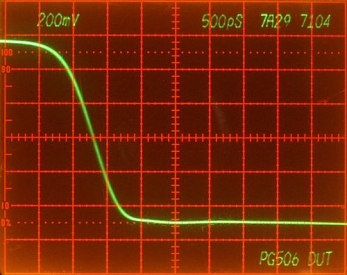
again an excellent measurement
Four Division Falltime about 750 Picoseconds
The real rise- and falltimes are a little faster, the sampler and
amplifier risetimes are included in these measurements. The only error
in this measuremnt is the user !!! He didn't adjusted the vertical gain
correctly, that's only a 20 second job, he feel ashamed. That's the
reason why he repaired the PG506, he don't want to see gain errors on
photos again.
PG506 Rise Time Measurement - S-6 Sampling Head
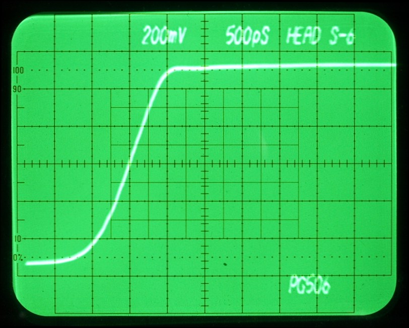
Measurement on a fast Sampling Head S-6, S-53 Trigger Recognizer, 7S12 TDR Plug-In in a
7834
Storage Oscilloscope. This S-6 sampling head has a risetime of
<=30ps equivalent to a 11.5 GHz bandwidth. The 7834 storage
oscilloscope operates in a variable persistance mode. A storage
oscilloscope combined with an sampling system is a very good
combination, allows good viewable low noise and high resolution
settings in a sampling system. The curve characteristic (settled
shoulder) measured with both sampling systems 7S14 and S-6 looks very
similar.
Four Division Risetime - measured with a S-6 Sampling Head - 800 Picoseconds.