Impressum und Haftungsausschluss


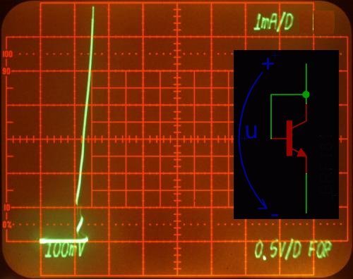
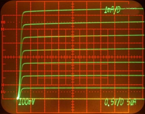
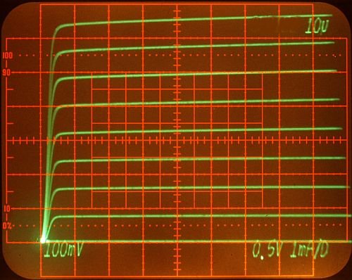
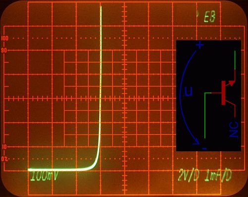
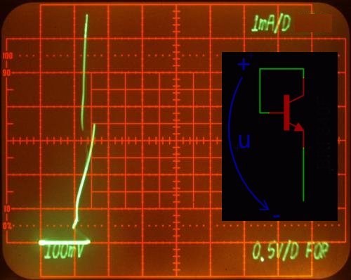
| The Base Emitter diode behaves like excepted, but in common Base-Collector diode the curve looks funny. The right curve is highly dependend from the way you are touching the transistor with your fingers or moving the curve tracer wires. Touching the transistor in a capacitive way the curve changes more and more to show normal diode curve behaviour. This is an indicator layout using a a common base collector diode will a be serious matter. At the moment I have no good explanation for the reasons. |


| The Base Emitter diode behaves like excepted, but in common
Base-Collector diode the curve looks funny. The
right curve is highly dependend from the way you are touching the
transistor with your fingers or moving the curve tracer wires.
Touching the transistor in a capacitive way the curve changes
more and more to show normal diode curve behaviour. This is an
indicator using a common base collector diode in a layout will
a
be serious matter. At the moment I have no good explanation for the
reasons. |

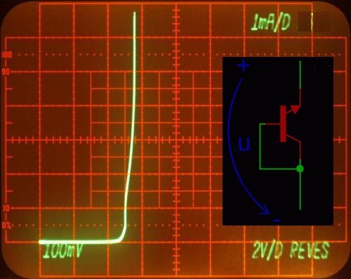
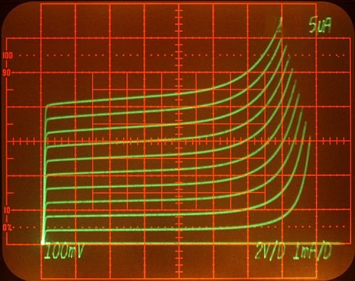
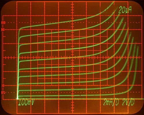
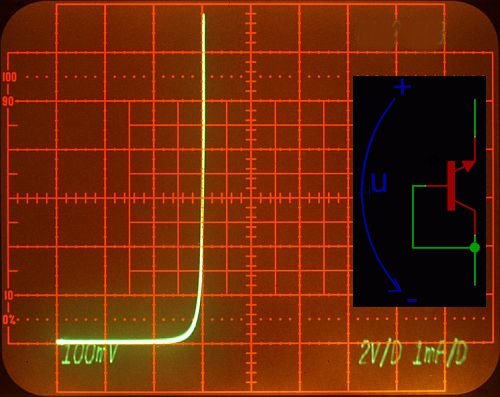
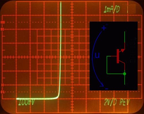
| At about 5 volts the reversed diode start to breaktrough. The common
Base/Collector diode shows again a strange curve. Also this diode shows
more and more normal curves when you start touching the DUT
in a
capacitive way with your fingers. But in this case the curves are not
so much dependend from parasitic capacitances like in the forward
connection. The maximum base current for this transistor is specified with a 2mA DC current, under the curve tracer the base current can be adjusted higher, because it's not a DC load. and the transistor should be still in the SOA. It's not the first transistor destroyed on a curve tracer. |