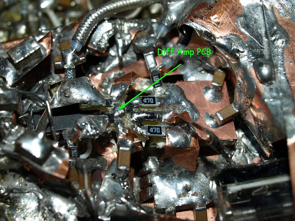
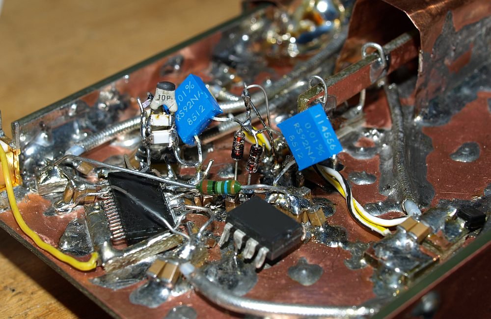
| I replaced the amplifier and current mirror transistors with the xxxx transistor. Mounted on a small selfmade epoxy PCB, resulting in higher spikes than before - I am disappointed. The epoxy seems to be a bad choice. Unfortunately these very small transistors can't be mounted on airwires only. |


| Using transistor xxxx with small wires soldered with symmetrical length. Also the diode array has now symetrical wires and got more distance to the ground. Transistors were selected on the Curve Tracer, for the current mirror. Results getting more and more better, mounting transistors in such a way seems to bring success. |


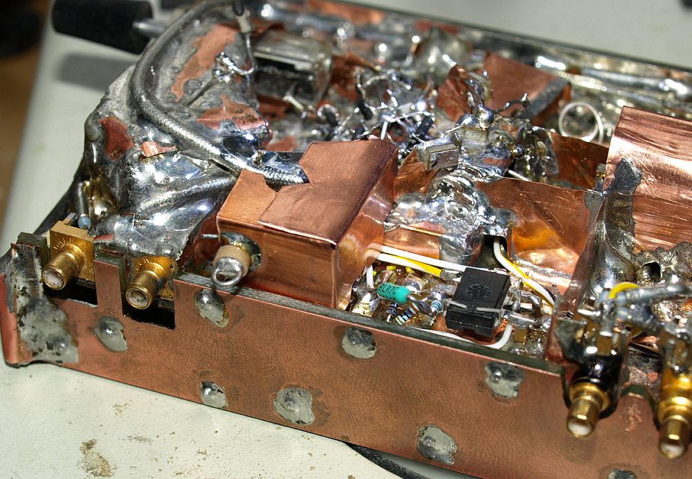

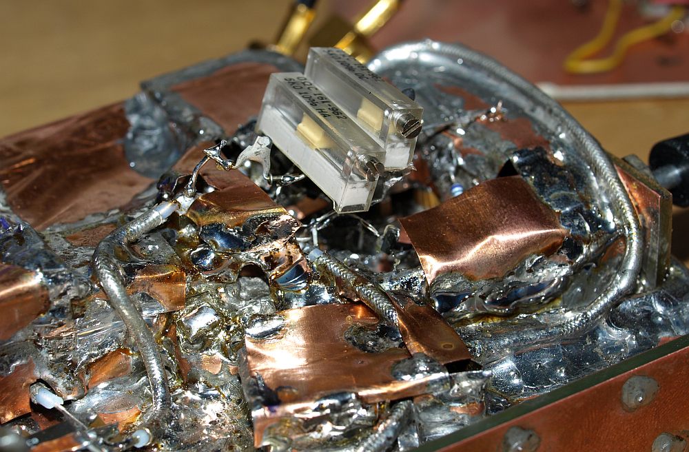
| Right SMB - Bridge Trigger Input |

| First trimmer
mounted. Copper
shield grows up - it's very important to test every single shield
which you fix to see a posible difference. If you change too many steps
at once and the result get worser, then you don't know which step
caused
the fault. I recommend this:
solder - test - solder - test - solder -
test........... this method costs a lot of time, but brings you
experience which changes cause which difference. |


|
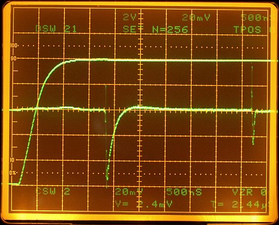
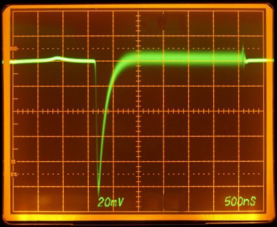
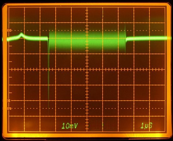
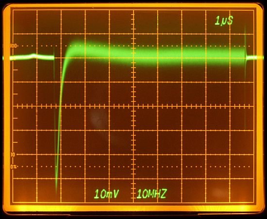
Result after trimming the bridge. Upper trace DAC output with 2V/DIV.
Using a 7A26 in 20MHz position plus 10 MHz RC lowpass filter. The window ON spike is very low now, the OFF spike only one division. Today I am not using my blue P11 phospor 7904 oscillocope, I have also a 7904 with the green standard P31 phosphor. Sometimes I change the scope on the workbench, it's like driving another car. The trace alingnment of this oscilliscope should be readjusted. |
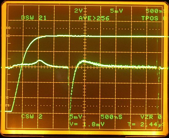
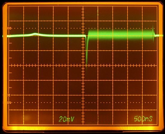
| Using a 7D20
digital scope Plug-In in the 256 times averaging mode. Same deflection factor settings as above. The 7D20 has a 70 MHz bandwidth, in comparison with the 20MHz of the 7A26 the spikes are a little higher. |


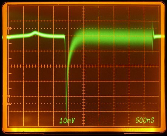
| Bridge with a long delay time shows both spikes now. The spike are
adjusted in such a way, that the ON spike goes to the screen bottom
first, this helps when showing the rising slope of the amplifier. The
OFF spike is adjusted to the smallest possible peak. (7A26 with 20MHz +
20MHz RC lowpass). |
| Some experiments, I want to replace the external pulsgenerator by a
simple Timer IC, saving space on the table, AC line power and the fan
noise from the generator. |
|
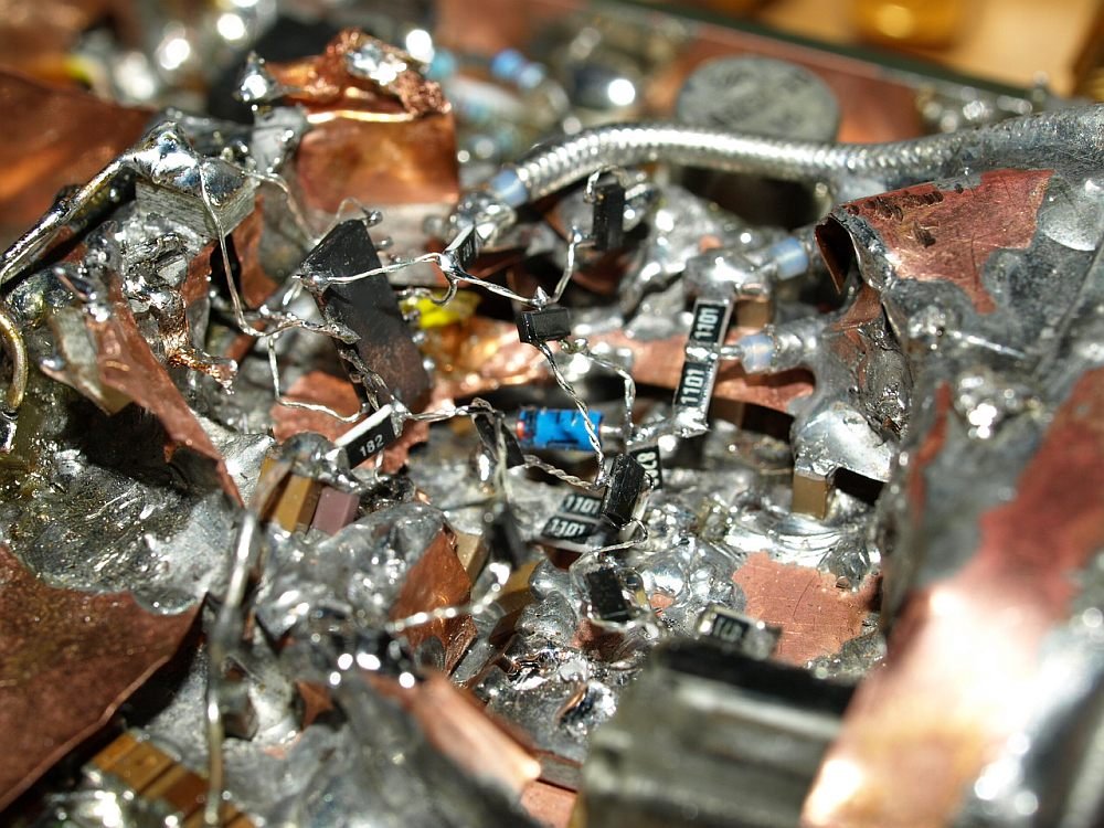
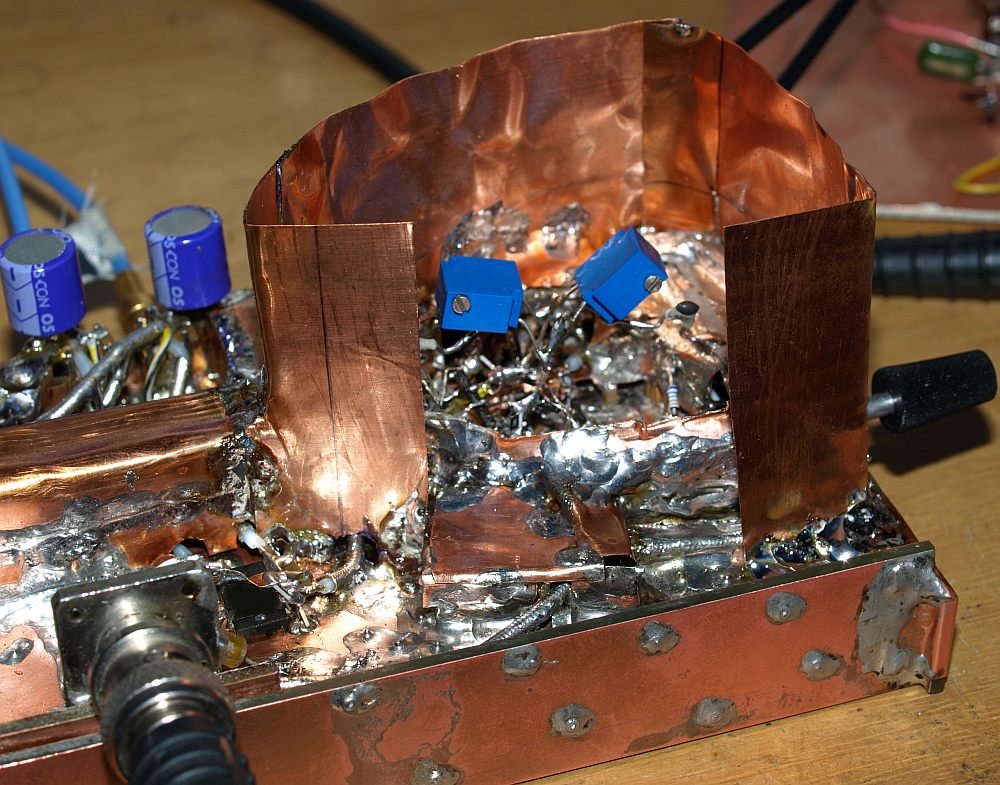
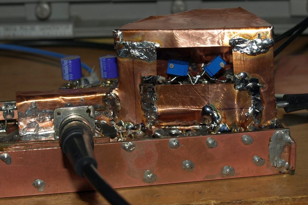
Smaller trimmers and a comfortable shielding. I did some improvements
with other transistor positions. The parasitic capacitance of the
transistors to the ground leds to different spikes. I reached after
many hours a level where I know which transistor cause the direction
and heigth of the spikes. Also some influence where the
trimmers are soldered on the net, some millimeters more or less and the spike
looks different. This experiments took me a lot of time. Mounting the trimmers close to the ground is terrible and increase the spike too much. That's why the shield around the trimmers is far away from this sensitive trimmers and the bridge nodes. |
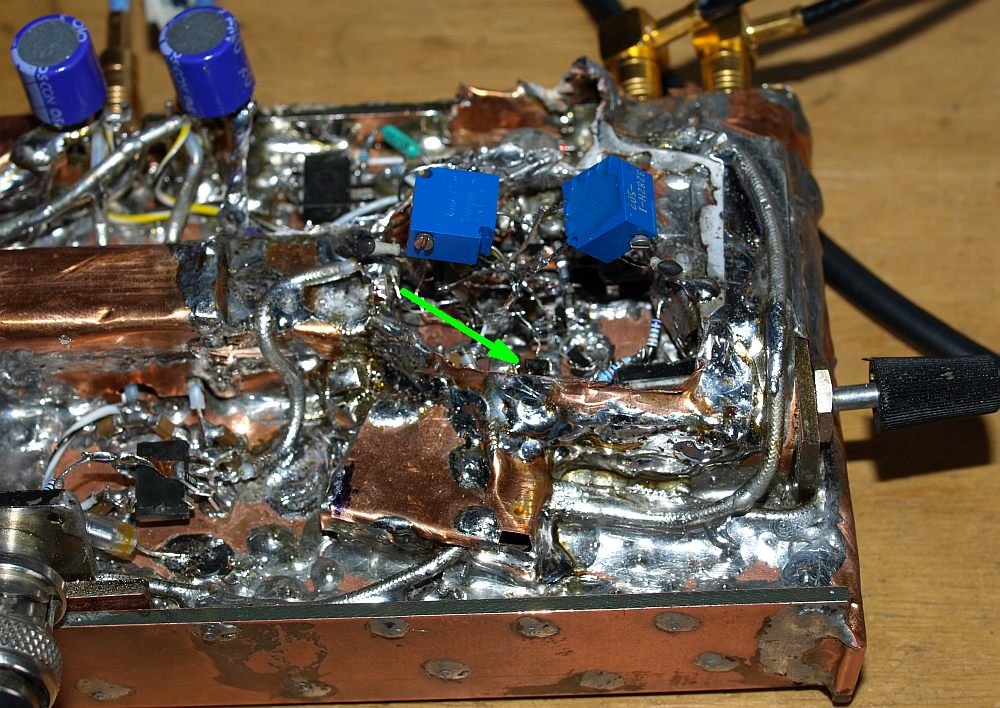
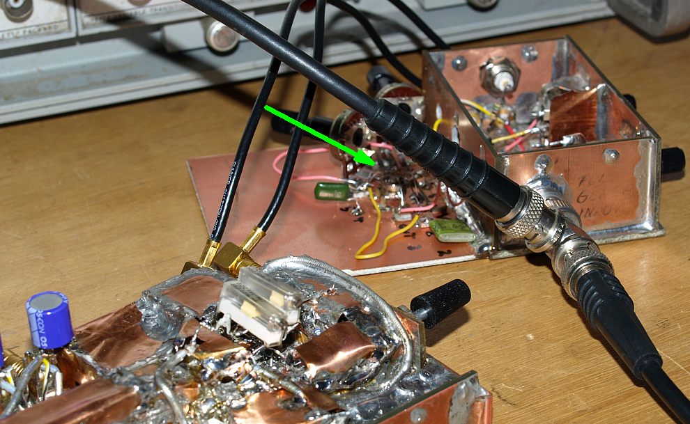
| For example, moving this diode-connected-transistor only a little more closer to the ground, the spike increase some millimeters on the scope. By finding the right position, spikes can be reduced. |

| I CHANGED THE RC LOWPASS
from 100 Ohms to 220 Ohms with 82pF, a 10 MHz -3db corner
frequency. I did it because I want the measure with the 7D20, and that
Plug-In measures with 70 Mhz and don't have a bandwidth limiter switch.
I also think it's a better idea to reduce the bandwidth direct after
the Residue Amplifier and not in the Oscilloscope Plug-In. The
220 ohms resistor helps also the xxxx amplifiers to isolate the
output better from the heavy capacitive 82pF load. The 20pF scope input
capacitance adds an additional capacitance. I completely removed the diode array heater circuit, because there was sometimes a very small HF oscillation, I don't know where it came from. No change to reject, trying many different capacitors to reduce the heater bandwidth, no change. I don't know, may be my unshielded heater wires acting as antennas, after removing the heater it was better. I don't need the heater, the instrument is stable. After burying in cooper, no air movement - the baseline stands stable enough - saves also current, because I thought also about battery operation. |


|
250µV/DIV with amplifier 7A26 in 200MHz position plus 10MHz
RC lowpass. The OFF spike is still within the CRT. Now you see a very
small rising window-ON spike. These small spike can't be adjusted with
the trimmers, it was only possible to minimize this small spike with
the position of the transistor described above. Also the noise level is
low, I guess the shielding helps for less noise. |

