Voltage Reference in
a DIY box
The voltage reference arose from the site effects of bending a reference
voltage. Gehe zu 
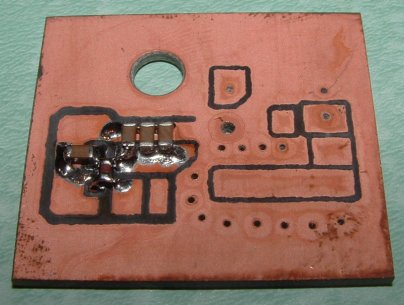 |
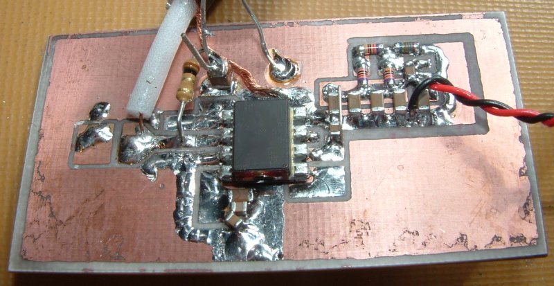
Everything has started with a small PCB used in another project.
|
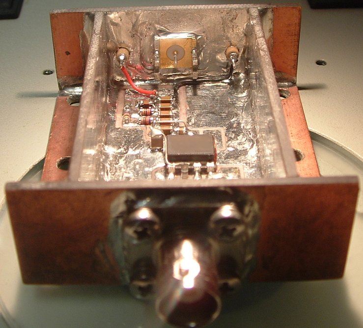
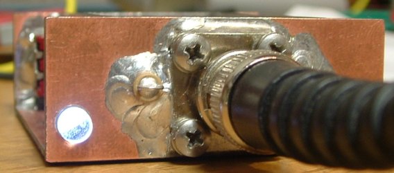
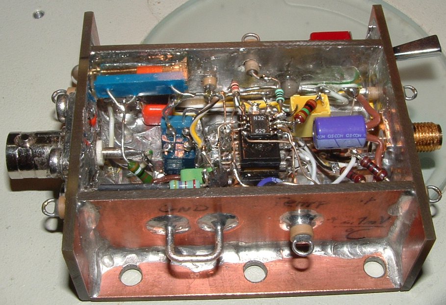
The coax forms a good ground
connection. It can be discussed if such a massive copper solder is
necessary, no question. We need not argue about, but it makes fun to
do.
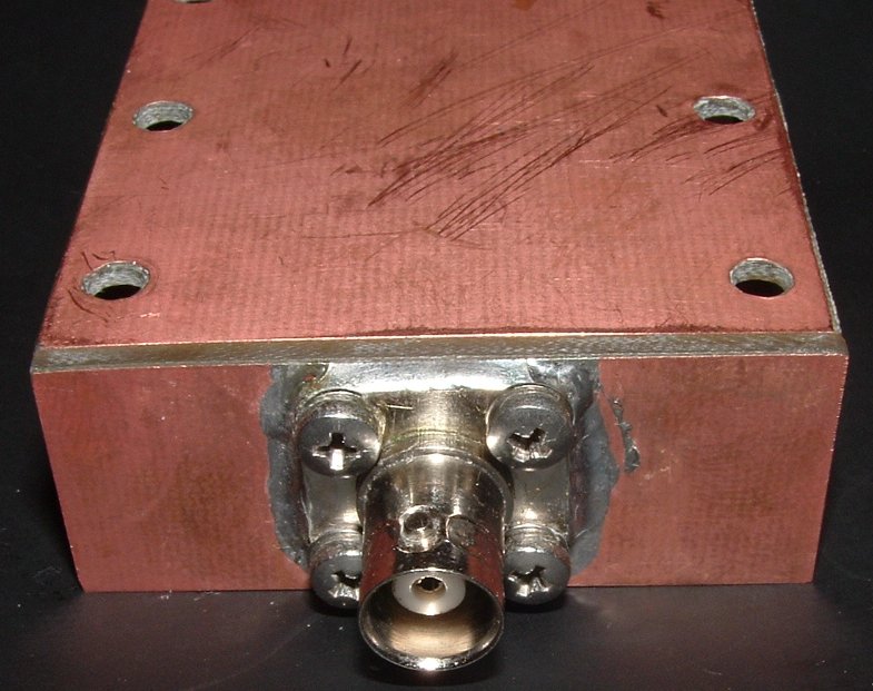
The nickel coating has to be scrated off with a sharp screwdriver, then
keeps the solder better on the coax carrier material. Screw threads
were cut into the epoxy. When soldering you should make sure not
to heat the white coaxial insulation too much, shortly
thereafter do not move the insulation, otherwise later a plug fits
anymore.
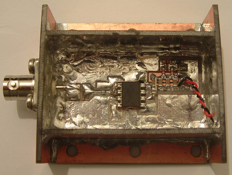
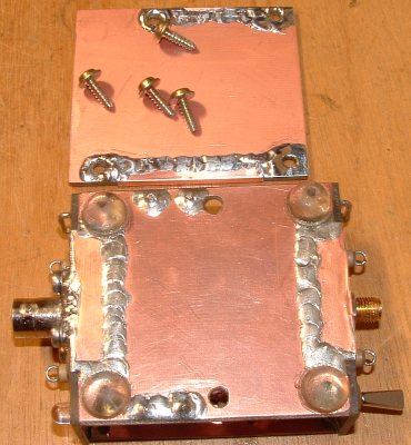
Epoxy material is excellent for building small DIY housings, good
emc, mechanically stable, solderable and affordable. Sawing with
a diamond blade saw, water saws are the most ideal for larger cuts.
When sawing, drilling, etc., from epoxy resin, it is highly recommended
using a respirator mask, this material in the form of dust in the lungs
is harmful.
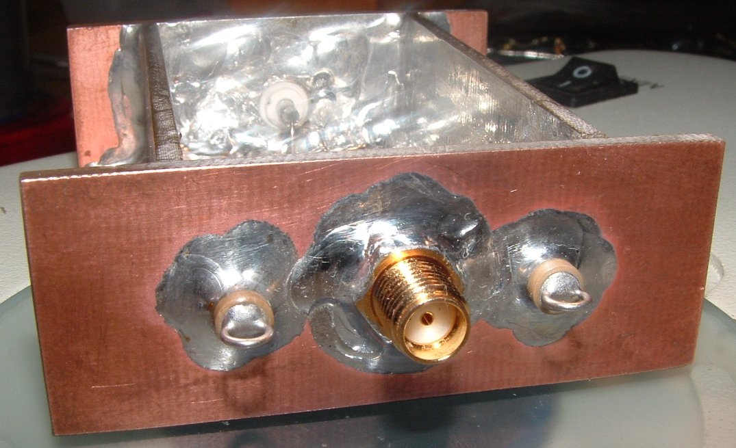
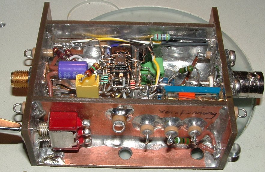
The golden SMA was found in a receycling container. Somebody doing
DIY electronic can't see people throwing away such parts. Two 160V/1nF
feedtrough capacitors rejecting high frequency emc. The capacitors were
bought on second hand market for a cheap price of 15 cents, byuing them
over a distributor could be an adventure.
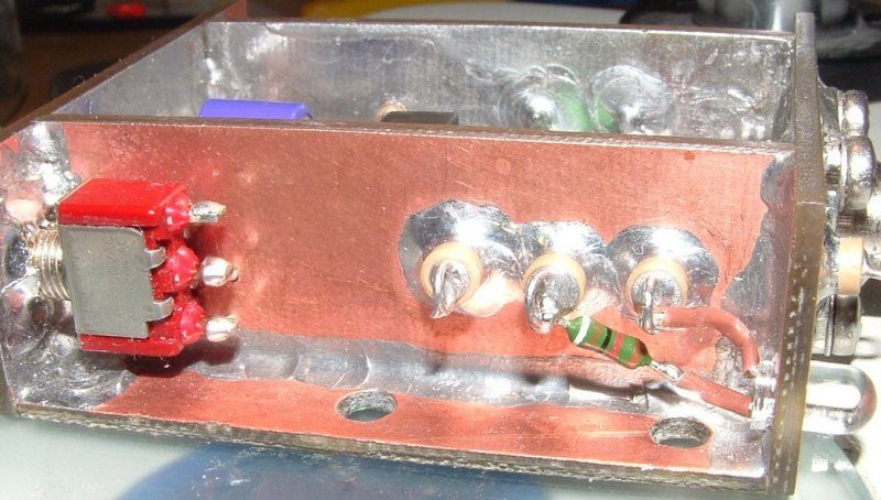
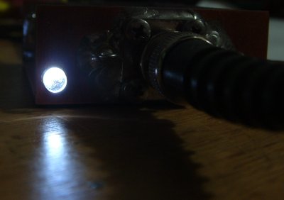
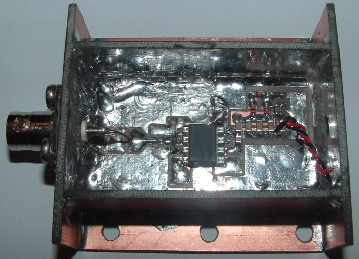
The withe LED indicates Power ON. A current of 100µA is already enough for an indication.
Everything is soldered, even the switch.
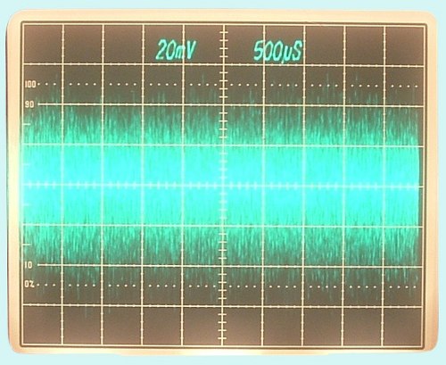
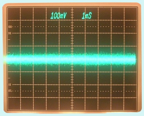
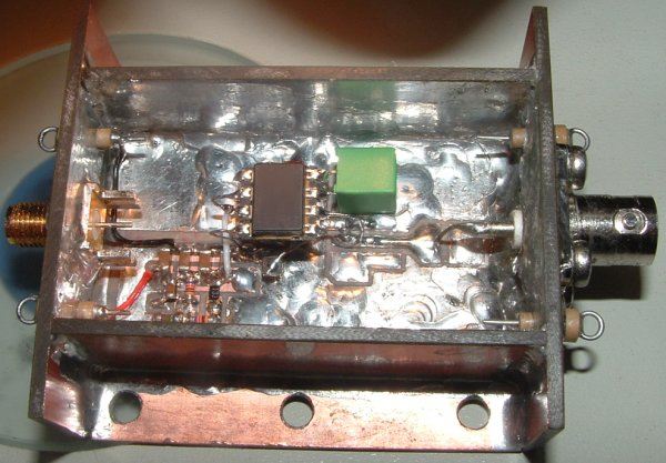
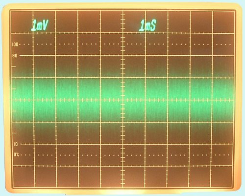
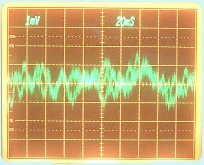
The reference is supplied by a low noise voltage regulator. Both traces showing the noise of the regulators, measured with my
Noise Indicator, Bandwidth 10 Hz to 100 kHz, Gain 1000.
(Vertical Resolution left 20µV / DIV and right 100µV / DIV).
Temperature Control
The circuit already has a low temperature coefficient, a constant temperature increase stability.
Test circuit for the temperature control
Finished - the trimmer sets the reference temperature over a small range.
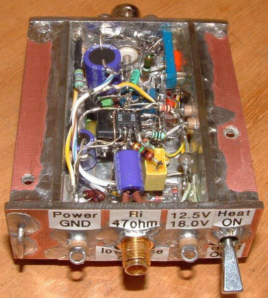
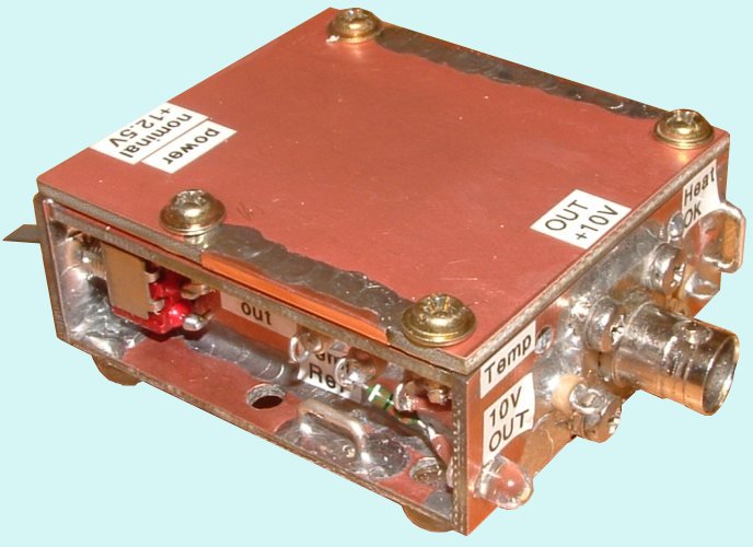
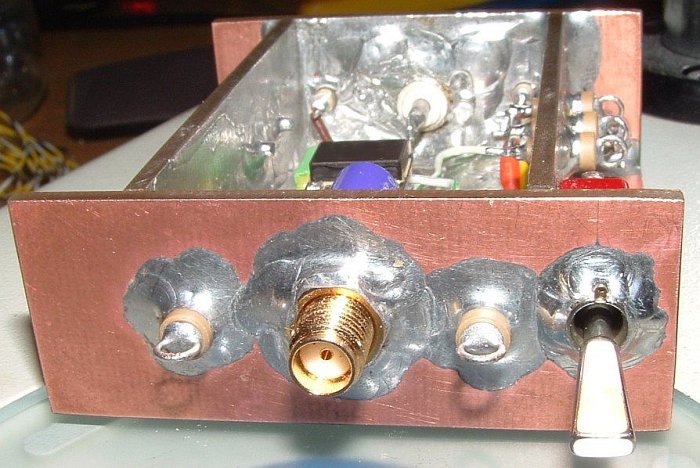
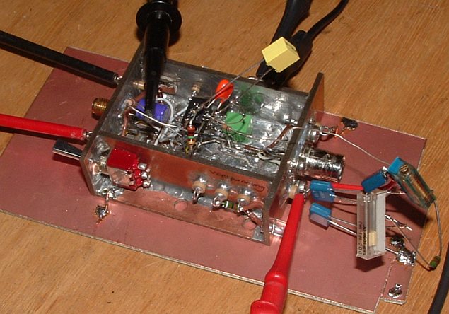
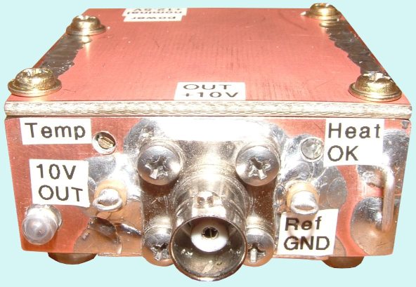
Every output and test point get a label. The srews taken from a old tape deck.
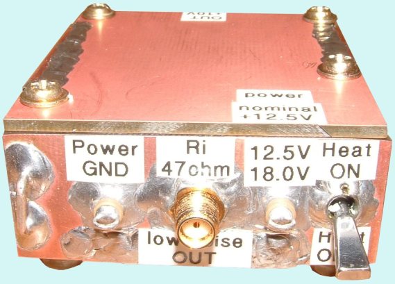
The trimmer sets the reference
temperature for some degrees, a blue LED indicates a Heater OK
condition, switch is for heater power. Nominal working
voltage 12.5V, good for an lead acid battery.
Noise Measuremt
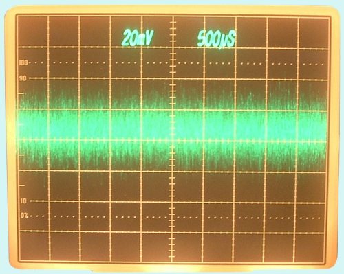
Noise Reference Output 20µV/DIV.
Bandwidth
10Hz -100kHz.
Noise on the
am low noise output 1µV/DIV. Bandwidth 10Hz-100kHz.
The 47 ohms 220µF low pass reduce noise. Unfortunately there is a
DC error caused by capacitor leakage currents. Also the internal 47 ohm
resistors reduce the number of useful application.
Easy task, the -3dB low pass cutt off frequency 15 Hertz.
Low Noise Output 1µV/DIV bei 20ms/DIV, additional use of an
7A22,
the upper corner frequency set 1kHz. Good to observe low frequency
noise. It's almost impossible to filter out low frequency noise,
absolute impossible for the noise in the frequency range of 1/hours.
Next build test equipment will be a 0.1Hz-10Hz filter.
Measurement Results:
Temperature changes in a chamber for
14 days, most time under high temperatures. Psot selection of the
references, searched for the ones close to the 10 V. Most devices were
below 10 V, the average of all 30 selected were 500µV below 10V.
Hard to find a piece close to 10V. I didn't wanted to use the
electrical trim via voltage divider.
Soldered and observed. After 10 minutes power on taken the first
measurement. Within the next half an hour voltage decrease 30µV,
the next 12 hour by another 50µV, after three days the reference
was much better. Now the part was close to 10V. With a little portion
of heat the reference reached exactly the 10V.
Temperature control, worked in a perfect manner, with
the psilloscope it was very easy making the control stable. The temperature
pin of the refence was stands still on the last digit of the DMM.
The voltage divider to set the
internal reference for the temperature control is derived by the 10V
output. An increasing 10V will increase also the reference temperature
output. On the temp-DMM the last digit stands still, the temperature is
stabil within the milli Kelvins.
It's not a good idea to calculate reference ageing, you can guess only.
In general with
increasing operating time the long time drift will decrease
significantly. You can't
predict how long the device needs to be stable.
Most references of the same type behavior and drift in the same
manner, this is a chance to give a prognonis. But what is stable? - you
find the answer in the demands of your application.
You can't calculate long time drift of references, the best method is test and wait.
Reference Measurement
Measurement setup, using not the best emf cables, good enough for the 10 volt range.
|
 |
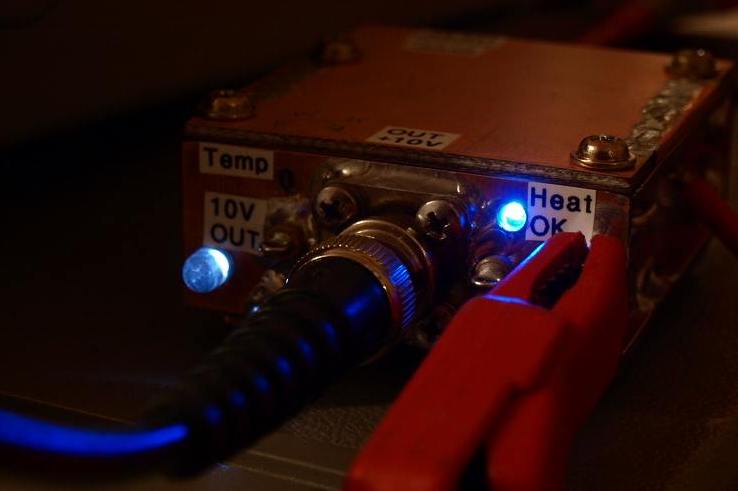
The blue LED indicates a settled temperature control. |
Long Time Drift
Since measurement 1140h, TC compensated measurement. Starting at t=1834h the reference got a new
Power Supply.
For this the reference was switched off, because some soldering were
necessary on the power supply pins. After this time without power and
heater after swithing ON again the reference shows a value some
10µV higher than before, even under controlled temperature. It
took some hours coming back to the old values.
It can be said the controlled IC temperature remains stable. A min.
max. range of 0.01 Kelvin is nice over a 1884h period, here even under
assumption of an ideal DMM. The new power supply leds to a
little increased temperature of +0.0025 Kelvin.
Temperature Coefficient Measurement - click here
Power Supply - click here
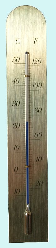
The room temperature. There were some days with an outside
temperature -3°C and some days with 18°C outside. This room
don't have an automatically controled heater. A family member
controls the temperature by "feeling cold - feeling
warm" switching the oven on or off. My respekt or her, stable over a long period. Always
measured in the morning and evening.
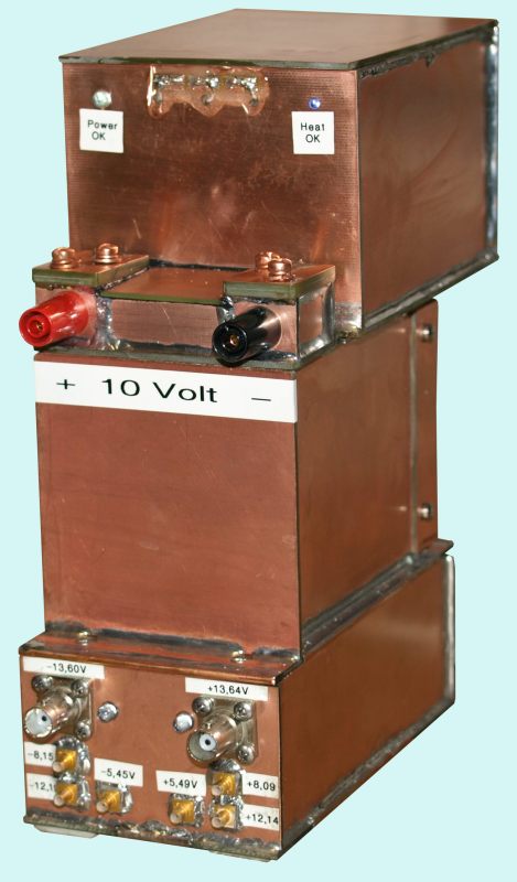
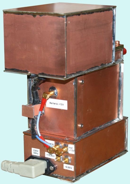
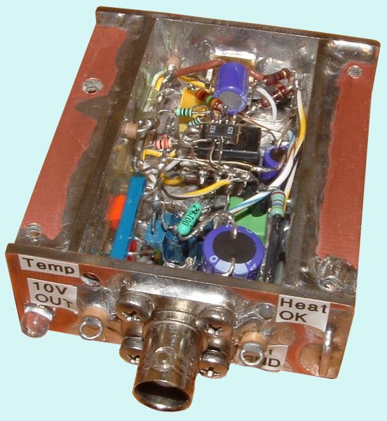
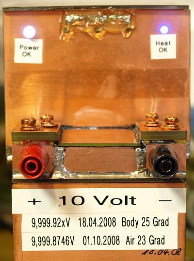
Now the reference mounted in a
small thermal isolated body. The coaxial connector was replaced with
4 mm banana plugs, better and more comfortable for DC
purposes. Over the plugs there are four copper srews.
Unfortunately it was necessary to solder near the reference IC,
therefore the former stable reference value of 9.999,58 Volt has
changed to more than 10 volts for some days. Now it is well stabilized
to approximately 9.999,92 volt, it was luck the value changed
closer to 10 volts after soldering and did not drift in the other
direction. If
the long time drift satisfies me, the reference will be measured on a
known calibrator.
This device looks funny, it was never planned build up such a
unit, it happened step by step and test by test. This reference for test purpose only. The power
supply current at room temperature reaches only 25 mA from a 12
volt battery, allows some days of battery powered operation.
Unfortunately the Temperature Coefficient is still approximately
-2ppm/°C even with this temperature controled body, I did somewhere
a design mistake. The remaining TC is
not the blame of the DMM, they work perfect and very stable over room
temperature. Experiments with different body ambient temperatures
show a TC behaviour corrosponding with the DUT. Some design issues are
under my suspision and I hope to cancel them out with my next
project.
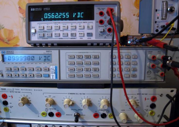
Calibration
Voltage measured with three
independent meter. The three meters are calibrated on three different
standards. The PT-100 is calibrated in a temperature controlled
oil-bath at 25°C oiltemperature. The PT100 was mounted with
heat-conductive paste.
| voltmeter |
measurement value |
PT-100 temperature during calibration |
body temperature DUT |
corrosponding room temperature |
date |
| Fluke 8508A |
9.999,917 volt |
110.472 ohm |
ca. 27.1°C |
ca. 25.1°C |
17.04.2008 |
| Datron 1281 |
9.999,920 volt |
110.430 ohm |
ca. 27.0°C |
ca. 25.0°C |
17.04.2008 |
| Fluke 732A, Datron DC-Kalibrator, DC Nullvoltmeter |
9.999,930 volt |
110.426 ohm |
ca. 26.9°C |
ca. 24.9°C |
17.04.2008 |
| resistance |
4-wire ohms (Datron 1281) |
temperature |
offset |
current |
slope |
ice-point (0°C) |
date |
| PT100 Standard |
109.591,70 ohm |
24.6°C |
0°C |
500µA |
not calculated |
not calculated |
17.04.2008 |
| PT100 DUT |
109.508,28 ohm |
24.6°C |
0.22°C |
500µA |
0.388209 ohm/°C |
99.95681 °C |
17.04.2008 |
Drift Measurement with three Multimeter
One day after the three DMM were calibrated with this 10V reference
under the same ambient temperature. The battery powered reference
should noit drift during transport.
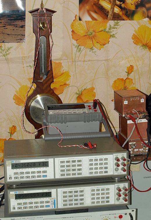
Photo shows meters during build-up.
One 3457 bottom (called No.20) the same one used in the former
measurements, another 3457 on top (called No.22) and the 34401 (called
No.34) in the back.
Meters are connected with single copper wires, the 34401 uses flexible
wires. One 3457 is programmed with the PT100 slope and offset, the
instrument indicates the temperature direct in Degrees Celsius. For
every measurement this instrument must be changed between 4-wire-ohms
and DC voltage measurement. The diagram continues at 2800h, time
elapsed since December 2007 (0h).
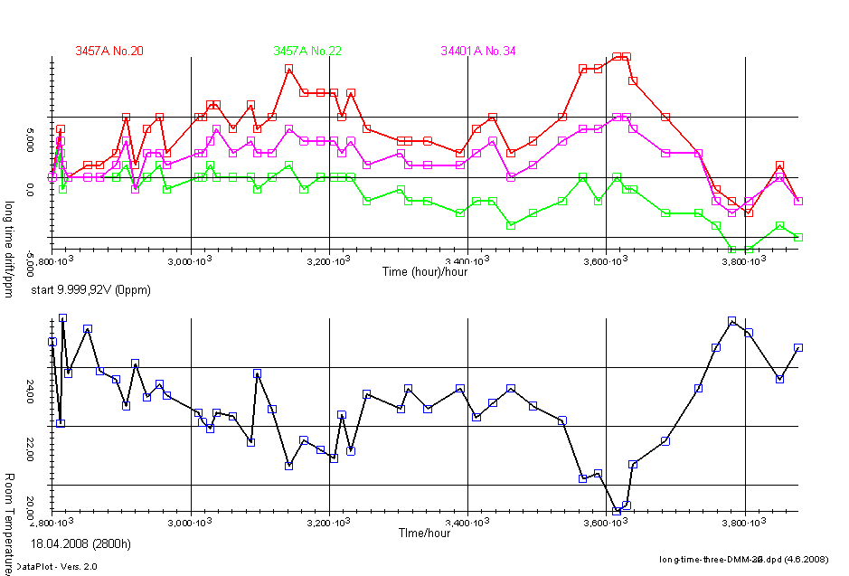
Which meter shows now the correct value? Which TC has the reference really?
The green DMM was connected at a later time, it was drifting after switching ON more than later.
The reference has a neagative TC, shown by all three DMM.
Summary
I'am satisfied, the next project will
have a better performance. The DMM are OFF now, Reference still under
power, measurement closed.
Measured half a year later
approximately -0.8ppm/month within the first year.
Measurement with another Reference
A bonus diagram of a 10V Reference in a small package, measured in another room with another DMM.
This reference is not temperature controlled, output load constant 6 mA.
Have fun and get experience with your own reference experiments.