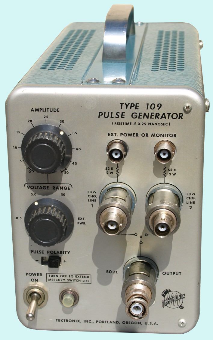
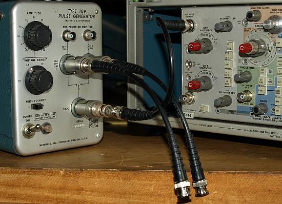
Type 109 Pulse Generator
Type
109 fast rise mercury switch pulse generator <=250ps
Der
Tektronix Type 109 ist technisch ein ganz besonderes Gerät, ein
sehr schneller Pulsgenerator mit schneller Flanke und bemerkenswert
flachem Einschwinghalten ohne nennenswertes Überschwingen.
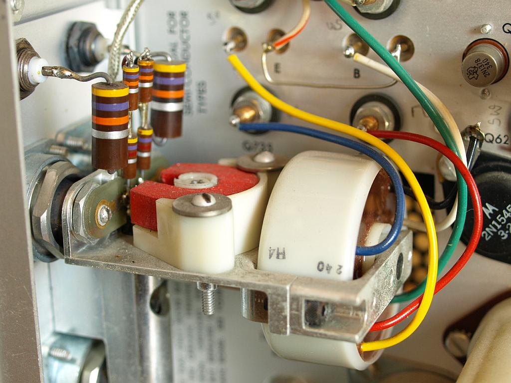
Erreicht wird dieses Verhalten durch das Schalten mittels speziellem
Doppel Quecksilber Relais, das mit ca. 550 bis 720 Hertz taktet ! Diese
Relais wird angetrieben von einem Ein-Windungs-Transformator, der die
hohen notwendigen Magnetfelder für ein schnelles Schalten liefern
kann. Das Relais befindet sich in einem Glaskörper, der zur
Abwechslung nicht wie bei Elektronen Röhren mit Vakuum evakuiert
ist, sondern mit Überdruck befüllt ist. Ein hoher Luftdruck
bewirkt eine schlechtere Ionisierbarkeit einer Funkenstrecke, deren
Ausbildung man an den Relaiskontakten vermeiden möchte. An den
externen Eingängen lassen sich noch höhere Spannungen
einspeisen, so dass in der enxternen Ext- Pwr. Position noch
höhere Impulse als 50V generieren lassen. Zur Nutzung dieser
Option sei das Manual empfohlen, das außerdem sehr
ausführlich geschrieben wurde, bei diesem Gerät ist es sehr
empfehlenswert das Manual zu lesen.
The
Type 109 is a special instrument, it uses a dual switching mercury
relais and two external charge lines. The relay is switching with a
frequency of approximately 700 actions per second. A strong magnetic
field cause the reed relay action, the field is generated by a one
winding transformer. The mercury is encapsulated in glass under high air
pressure. A high pressure rejects gas ionisation und avoid/rejects arcing
during switching. Reading the manuals of this generator is highly
recommendated, it's written very detailed and explains in many examples
how to operate.
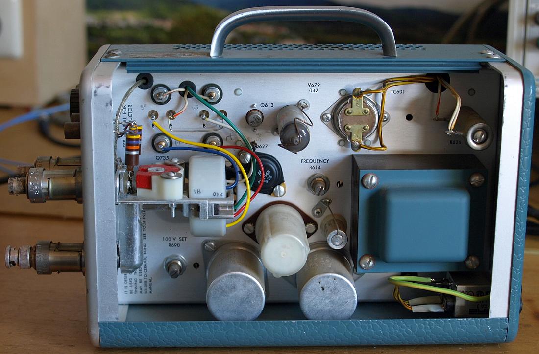
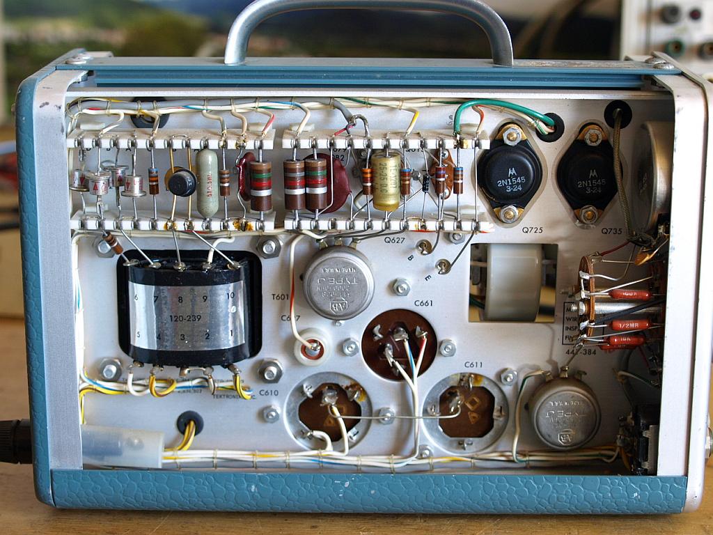
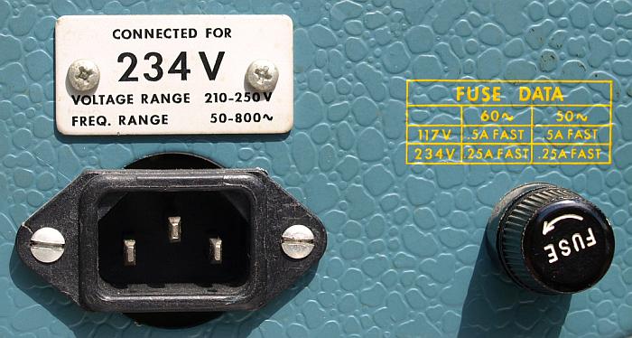
Aufgesteckt auf die originalen GR-874 Buchsen befinden sich Adapter auf
BNC. V679 a 105V voltage regulator tube. TC601 overtemperature
protection. R614 adjust mercury switch frequency.
Mercury relais most left, transformer right. The relais operates only
in a standing position, don't operate the generator upside down.
Screenshots of the Type 109
Der 109 hat bedingt durch das
mechanische Prinzip eine relativ geringe Wiederholrate des Impulses.
Setzt man diese Wiederholrate in Bezug auf die sehr kurze Zeitdauer
eines Impulses kommt man zur Erkenntnis, das hier nur sehr selten etwas
aus dem Generator rauskommt. Sagen wir mal 700 Impulse pro Sekunde,
dann sind das alle 1.4 Millisekunden ein neuer Impuls, die Impulsdauer
beträgt ca. 1.4 Nanosekunden, das ergibt 10 exp-3 / 10 exp-9, ein
dargestelltes zeitliches Verhältnis von Eins zu einer Million was
das Oszilloskop noch darstellen muss. Diese Anforderung für
periodische Signale erfüllen beispielsweise schnelle analog
Speicheroszilloskope
7834 oder im Real Time Betrieb natürlich noch bequem das
7104 mit seiner hohen Leucht Intensität der Röhre. Zum Beispiel selbst das schnelle
7904A und
7904
werden bei der Darstellung dieses Impulses ziemlich blaß,
von einfachen Geräten ist gar nicht mehr die Rede davon, da
muss man schon stark den Raum abdunkeln um noch den Impuls zu sehen.
Zur Beobachtung von Signalen mit dem 109 sei ein 50 Ohm Sampling System
empfohlen. Ein Sampler hat die Eigenschaft die steile Flanke und den
nachfolgenden Übergang in den flachen Bereich sehr präzise
darzustellen, sein bekannter Nachteil ist er kann prinzipbedingt
nur
periodische Signale darstellen. Wird der Sampler in einem analogen
Speicher Oszilloskop verwendet so ensteht auch ein durchgehend klarer
Kurvenzug. Die Verwendung der dicken RG-8 Kabel mit GR Anschlüssen
sei empfohlen, falls vorhanden. Als Betrieb mit einem analogen Real
Time Oszilloskop ist ein
7104 zusammen mit
dem
7A29 zu empfehlen, eine ideale Kombination für diesen Impuls.
Selbstverständlich können auch all die heutigen modernen
hochwertigen Digitaloszilloskope verwendet werden, die haben mit der
Darstellung
selbst von einem Single Shot natürlich keine Probleme, aber eine
Bandbreite von 1 GHz und eine entsprechende Abtastrate sei schon
empfehlenswert. Die Sampler der vergangenen Tage haben die
exzellente Eigenschaft das Signal präzise darzustellen, Tektronix
baut auch heute noch Sampling Oszilloskope, derzeit werden in
Spitzengeräten Bandbreiten von bis zu 70+ GHz (2008) erreicht bei
Anstiegszeiten im unteren Picosekunden Bereich, ein Blick in deren
Verkaufsprogramm ist eine Freude zu sehen wo die enorme
Leistungsfähigkeit heute angekommen ist.
For observing Type 109 pulses use a 50 ohms sampling system
together with a analog storage oscilloscope. A sampling system has an
excellent settling behaviour with almost any overshooting. The low
repetitive rates of this generator makes a storage oscilloscope
helpful. When using a analog oscillocope a bandwidth of 1 GHz is a
good choice, use a 7A29 amplifier togehter with a 7104 or 7904A
mainframe or
at least a 7A19 amplifier. When using modern digital scopes take
care that the instrument has
also a high bandwidth of 1 GHz or more. Of course any other slower
scope can be used, but consider catching and triggering a short 250ps
pulse under low repetitive rates it is a hard job for a scope.
Many scopes in the labors are too slow and many
analog scope having problems showing a bright beam under the low
repetitive rate of this generator. Tektronix still build modern
sampling scopes, they reach about 70+ GHz bandwidth nowadays (2008).
Viewing
the curve with a 7S14 sampler was very easy, plug-in has a good trigger
capability, with
my 7S12, S-6 and S-53 I had no luck to catch this pulse, may be I did
something wrong. If available use the RG-8 coax cables (high diameter)
and GR-874 connectors and avoid adapters to BNC or SMA systems.
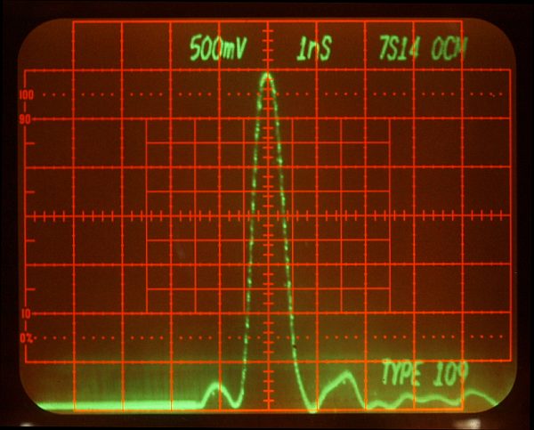
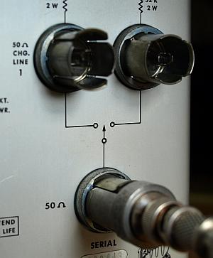
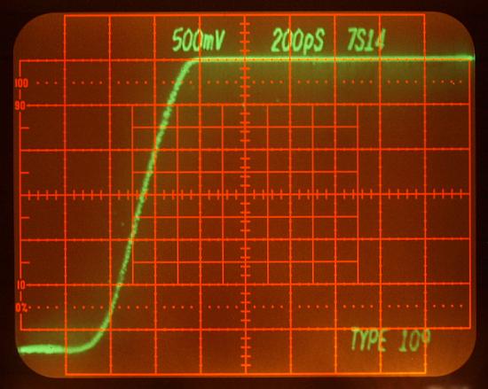
Photo shows the shortest possible pulse. Both GR-874 output left open. Measured with a
7S14 Sampling Unit in a
7834 Storage Oscilloscope
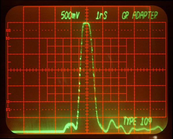
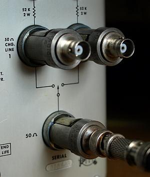
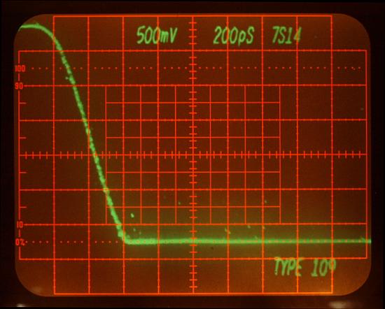
Photo shows the puls when there are to GR-874 to BNC adapters mounted, their short charge line already increase the pulse-width.
When the charge lines left open the Type 109 always prodcue two
alternating pulses, if both charge lines having the same length and
impedance, both pulses are overlayed and only one is observeable.
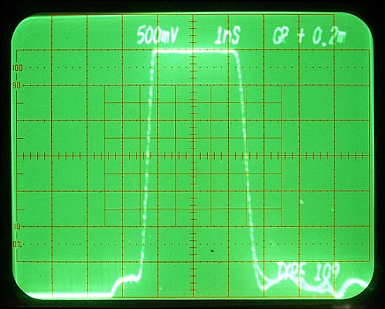
Fast rising pulses very flat
without any overshooting. This generator is really a beauty in the
world of test equipment. The often used tunnel diode pulsers and
avalanche transistor pulsers having a lot of advantages, but which
system will beat this flat mercury pulse response? Unfortunately not for every
amplitude setting the pulse was flat like in these photos, only in some, so don't be
disappointed when it's not flat under many amplitude settings.
The
two step response photos above they show a problem ! The real response
is unfortunately not so flat as shown in the photos ! The sampling
plug-in was in a saturation !
When reducing the amplitude level,
an excepted ringing can be observed, still very excellent but
unfortunately not so flat as the photos above. Such a flat response
would be too nice.
Realized when I used the 109
again. I don't want to remove the old text and the photos, because the
saturation effect was for me a new experience and my be also for you.
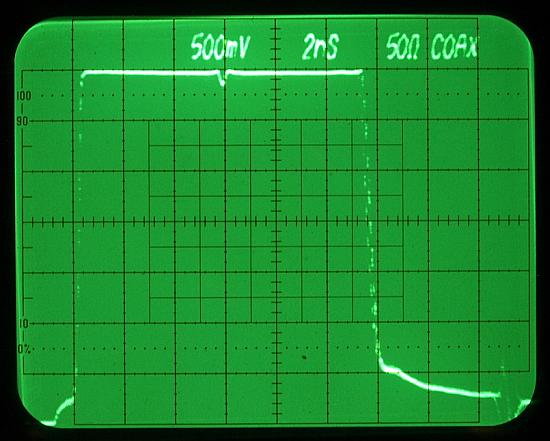
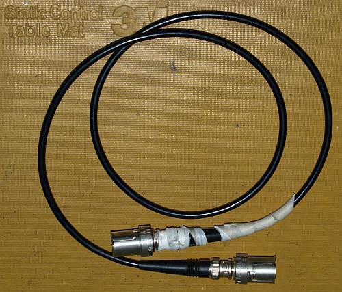
Using only one cable on both charge
line outputs. Measurement uses a 50 ohms RG58 coax cable of 1
meter length (don't care for the
tape around). Flat pulse, the negative spike in the
middle comes from a reflection during switching action of the
relay. This single cable operation overlays both pulses to one, with
the
spike in the middle. It is said that one meter RG cable cause a delay
of
approximately 5ns - see the timing in the photo, it's true. Distance
from the edge to the spike about 5.8ns, that's expected for 1m cable
plus two
GR-BNC adapters.
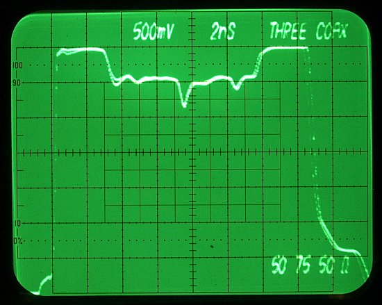
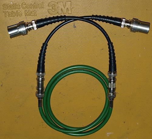
Using three coaxial cables as charge line.
GR adapter - 20cm 50ohms coax - BNC/BNC adapter - 90cm 75ohms video cable - BNC/BNC adapter - 20cm 50 ohms coax - GR adapter.
The shown charge line don't have a constant cable impedance of 50 ohms, the middle
segment has a 75 ohms impedance. The CRT shows clearly the impedance
jump from 50 to 75 ohms along its way on the cable. Exactly in the
middle there is still the spike caused by the relay action.
This cable would be a bad choice for high quality high-speed signal
transfer, for analog and digital signals.
A charge line pulse generator is a powerful instrument with many possibilities.
Reading and understanding this screenshots need some experience,
but the manual helps a lot to learn how to operate this generator.