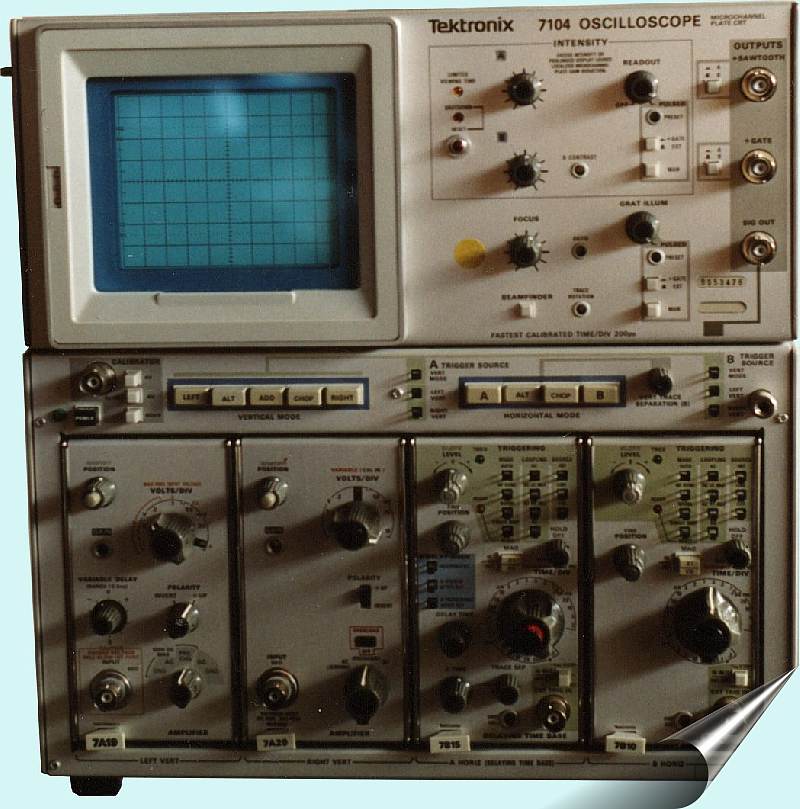
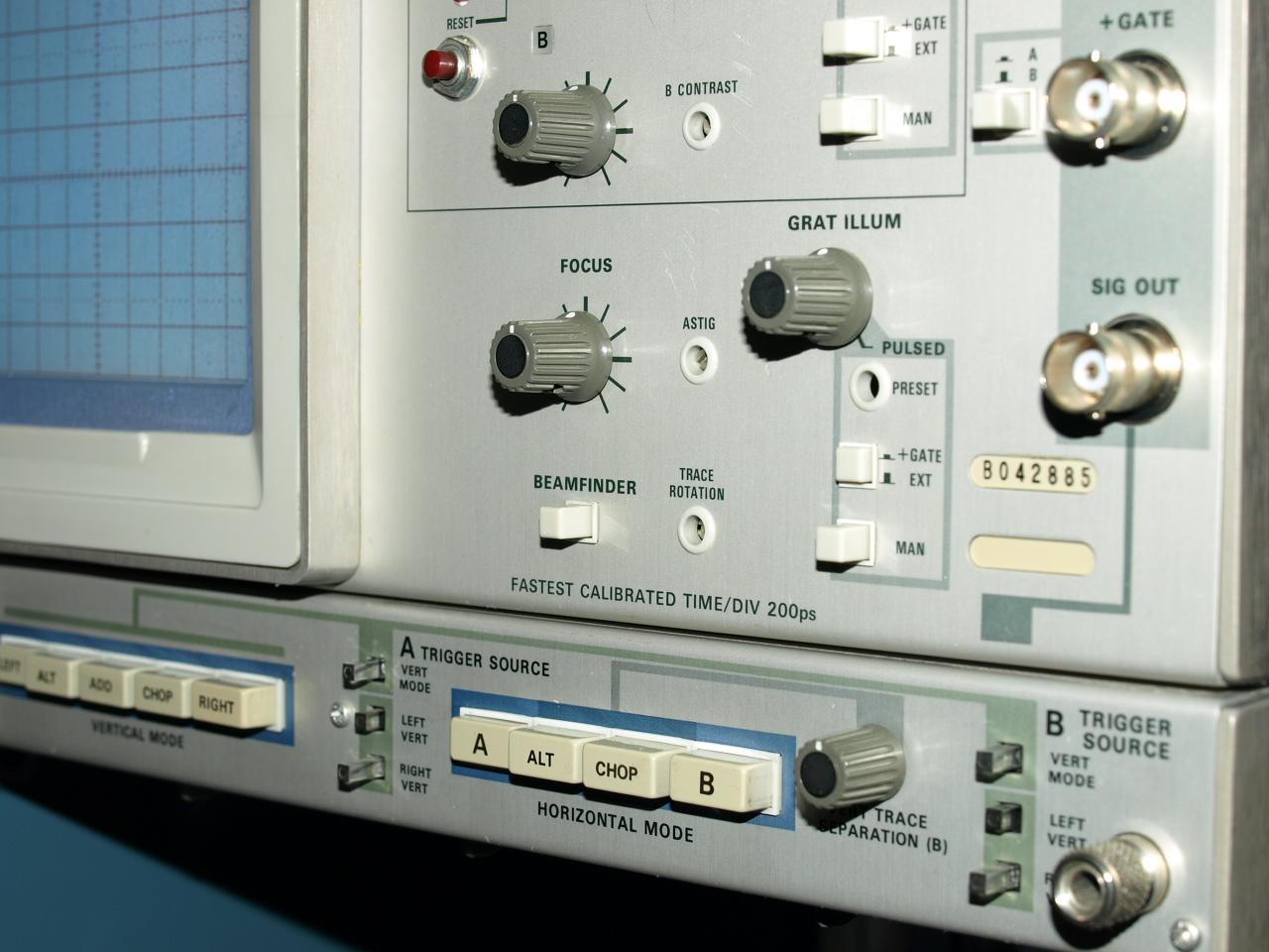
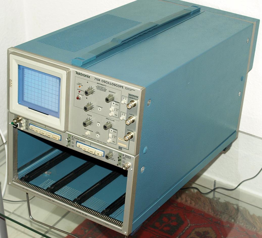
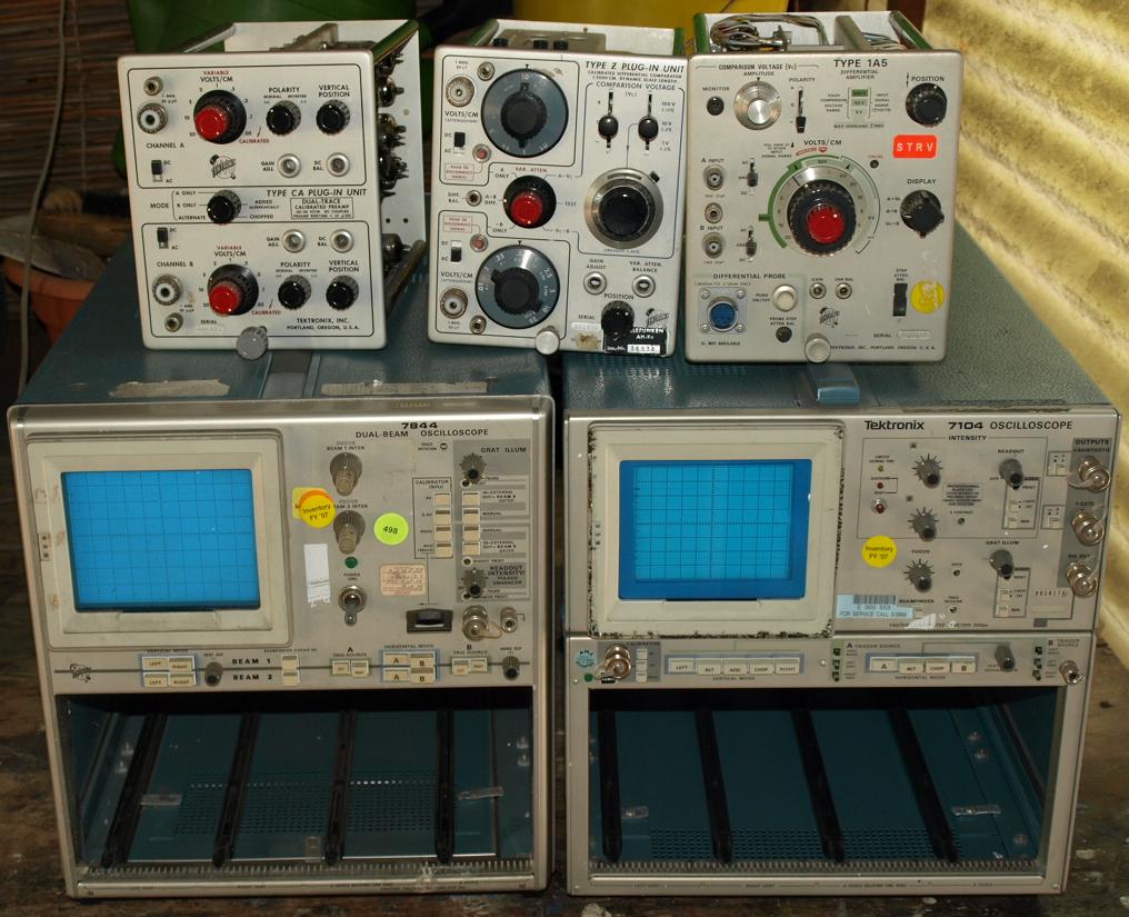
7104 Oscilloscope
Das Tektronix
7104 ist ein Analog Oszilloskop mit einer Bandbreite von 1 GHz in
Verbindung mit einem 50 Ohm Vertikalverstärker Einschub 7A29.
Schnellste kalibrierte
Horizontalablenkung 200 Pikosekunden/Skalenteilstrich. Die schnellen
Zeitbasen 7B10und
7B15 sind
für die Verwendung in diesem Oszilloskop zu empfehlen. Die
meisten anderen 7000er Einschübe können auch
verwendet werden, jedoch nicht alle (bitte siehe im Manual, manche
Einschübe sind ausdrücklich nicht erlaubt). Es ist
eines der
schnellsten (oder
das) analogen Serien-Oszilloskope, das je gebaut worden ist. Die
eingebaute Micro
Channel CRT ist eine Sonderbauform, die diese schnelle Zeitablenkung
darstellen kann über eine extrem hohe Schreibgeschwindigkeit
verfügt und eine hohe Helligkeitsdynamik besitzt, selbst nur
kurz
erscheinende Signale werden gut dargestellt.. Die genauen technischen
Daten und die Anwendungen können aus den
Katalogen oder dem Manual entnommen werden, beides ist im Internet zu
finden.
The Tektronix
7104 Oscilloscope is one of the fastest analog scopes ever build. It
has an bandwith of 1 GHz using a 50 ohm 7A29
vertical amplifier. The
7B10
oder 7B15 time base
allows an fastest calibrated sweep rate of 200 picoseconds/Division.
See the catalogues and the instruction manual for technical details and
specifications, both papers can be found in the internet.
First shown 7104 on this website:
 Heike und Andreas
danke für das allererste Bild von diesem Oszilloskop, es wird
bleiben.
Heike und Andreas
danke für das allererste Bild von diesem Oszilloskop, es wird
bleiben.
Second shown 7104 on this website:
Screenshot:
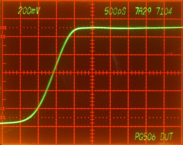
Shows the fast rise output of a
PG506,
with a
7A29
amplifier in a 7104 mainframe, extra readout information comes from a
7M13
unit. Photo taken with a Olympus E-510 four-thirds digital camera with
35mm macro lenses.
Die micro channel plate Röhre hat den Vorteil, das sie seltene
erscheinende Signale noch mit voller Helligkeit darstellen kann. Fast
alle anderen Oszilloskope mit Standard CRT zeigen bei einigen
besonderen Signalformen gar nichts mehr, während das 7104
diese
Signale noch fangen kann. Gerade im Hochgeschwindkeitsbereich von
Digitalsignalen können damit z.B. Trigger Ausreißer
dargestellt werden, oder selten auftretende Formen von Jitter, Implusen
usw. - siehe Kataloge -. Diese Röhre hat nur eine
Größe
von 0.8cm/DIV im GEgensatz zu den üblichen
größeren
1cm/DIV Röhren.
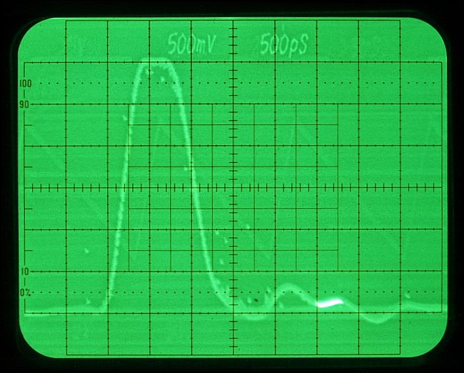
The micro channel plate has not only the advantage under low repetitve
signals, the beam can focused also very sharp, see the sharp readout
numbers, that's brilliant. This CRT has only a 0,8cm/DIV dimension, not
the widely used bigger 1cm/DIV CRT.
Ein deratiger Helligkeitsvorteil hat auch seine Nachteile:
die 7104 Röhre muss sehr pfleglich behandelt
werden, die
Strahlenergie kann bei diesem Röhrentyp sehr schnell
permanente
Einbrennspuren verursachen. Um den Benutzer auf einen zu hell
eingestellten Strahl hinzuweisen hat der Hersteller neben der CRT eine
gelbe Leuchtdiode platziert, die anfängt zu leuchten als
Hinweis
bitte die Strahlstärke zu reduzieren, wird dies ignoriert
erfolgt
nach ca. 20 Minuten eine automatische Abschaltung. Die Leuchtdiode ist
zweistufig, fängt sie an zu blinken soll möglichst
sofort die
Strahlstärke reduziert werden, ansonsten erfolgt die
automatische
Abschaltung sehr bald.
Man soll nicht der Auffassung sein durch diesen optischen Warnhinweis
in Verbindung mit der automatischen Abschaltung sei die Röhre
sicher gegen Einbrennen, das ist sie nicht. Ich möchte es
nicht
probieren, aber bei voll aufgedrehter Helligkeit und passenden Signalen
können sicherlich wenige Sekunden ausreichend sein um
Einbrennspuren zu
verursachen. Anderseits muss das Gerät kurz die
Möglichkeit
geben die Strahlstärke voll auszunutzen um gerade seltene
Ereignisse im Signal darstellen zu können. Ein ganz einfacher
Vergleich, sehr leistungsstarke Fahrzeuge lassen dem Benutzer auch die
Möglichkeit die Leistung vollends auszunutzen ohne ihn zu
beschränken, wer da nicht bedacht und erfahren an die Sache
geht
kann die Folgen erahnen, bei diesem sehr leistungsstarkem Oszilloskop
ist das genauso.
The yellow LED warns the user about a too high CRT intensitiy,
after 20 minutes the instrument shuts down. If the LED blinks you
should reduce CRT intensity soon as possible, after some minutes the
instrument shuts down. The LED remind the user not to set intensity too
high - beam energy burn-in phosphor. This micro-channel CRT is very
sensitive, use it with care. I don't want to test it, but I think some
seconds under full intensity combined with suitable
signals burn-in the CRT already. It's a very powerful
instrument,
but like a muscle car it needs a good user.
Searching for burn-in
marks:
Beam settings in the photo above:
- reduce room light to a lower level
- reduce beam intensity to a minimum
- set the vertical amplifier offset so that the beam leaves
the CRT viewable range (on the photo beam hidden below the bottom horizontal grid line)
- increase the intensity very slowy that the beam starts
illuminating the screen by reflected diffusion light
Photo with burn-in marks in a used 7104:
- On top and bottom there are the readout marks.
- On the vertical 4.th division there is a clearly visible
straight line, the beam stands often there.
- On 2.nd and 3.rd vertical division beam stands there also
many times.
- On vertical divisions > 4, beam stands there seldom.
Fortunately there are no big marks or signal curves from misuse, thank
you former user my dear. These marks are typical for a normal
operating history and they are not visible under normal operating
settings, on the areas with burn-in marks MCP sensitivity is reduced.
My recommendations:
- use the 7104 not for daily use,
take better a 7904A,
7904, 7844 or 7704A.
Use the 7104 working with important applications,
excepted new unknown signals, fast signals, troubleshooting
in high speed circuits, expecting low repetitive signals mixed with
standard
repetitive signals or just when you feel like using it for fun.
- use the readout in this CRT in a less intensified position, reduce
it always to a minimum viewable level or switch it off for continous operation.
- reduce the room light to a minimum level, allows a reduced CRT intensity. Of course this CRT has the power for
operating excellent under day-light, but why forcing the instrument
showing it's full power?
- use a viewing-hood and reduce intensity
- don't give any stupid engineer or any other children a
chance
working with this instrument. In my life I've seen many engineers
using scopes like a TV, operating powered ON for hours,
sometimes
powered over the weekend - unused - many times with
a high
intensity. Give these people onetimes a 7104 in their hands - they will
burn-in a trace in the CRT for sure. They are the same people who are
careless with probes, mostly the ones with high salaries and good
skills in talking and rhetoric, later they will say: "it wasn't me".
Take care for these wonderful instrument - manufactored anymore.
Another example how a
burn-in mark in a CRT looks (7834):
This is a CRT photo from
my
7834
storage oscilloscope operating in the "Bistable Mode". Shown there is a
waveform of a Type
109
Pulse Generator. In the background you see a
triangle waveform and some horizontal lines, burn-in traces,
they
disappear anymore. It seems there was too much intensity and beam
energy on the
CRT, I don't know under which intensity the trace stands and for how
long. Fortunately that's the only operating mode
showing marks, other modes don't show.
Third shown 7104 on this website:
I've got another 7104 in working condition, "buy as is", I'm a lucky
guy receiving an 7104 in an almost perfect optical condition, manufactoring year appoximately 1984.
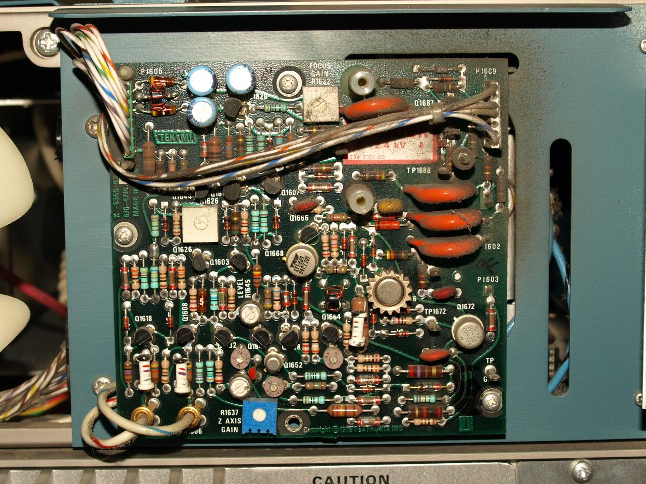
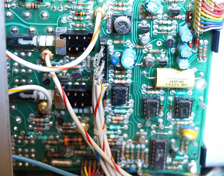
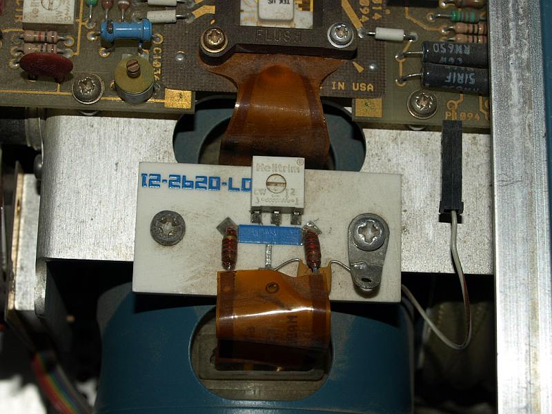
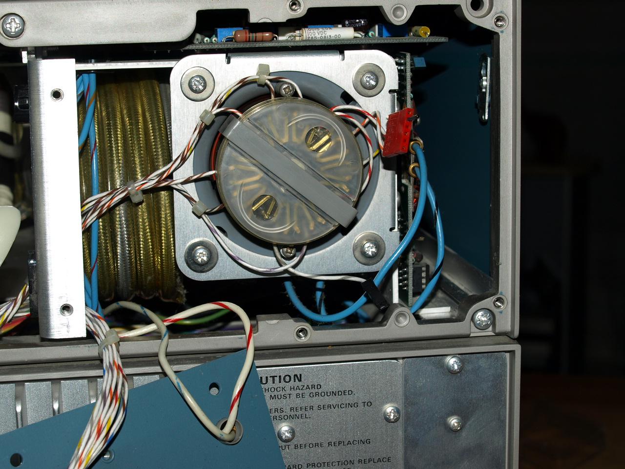
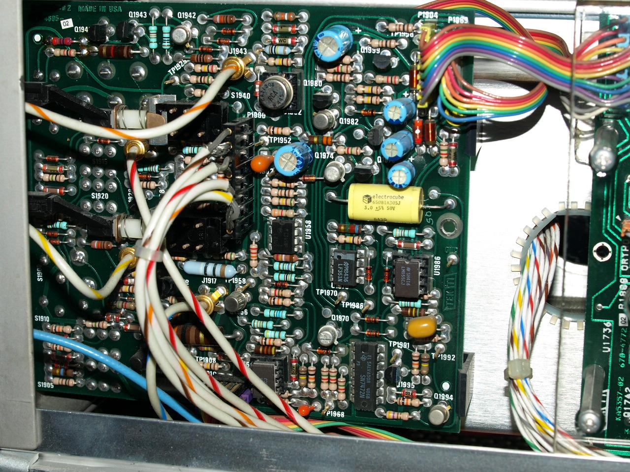
Z-axis amplifier before cleaning, dust near the high voltage parts.
After removing the amplifier and cleaning the cabinet.
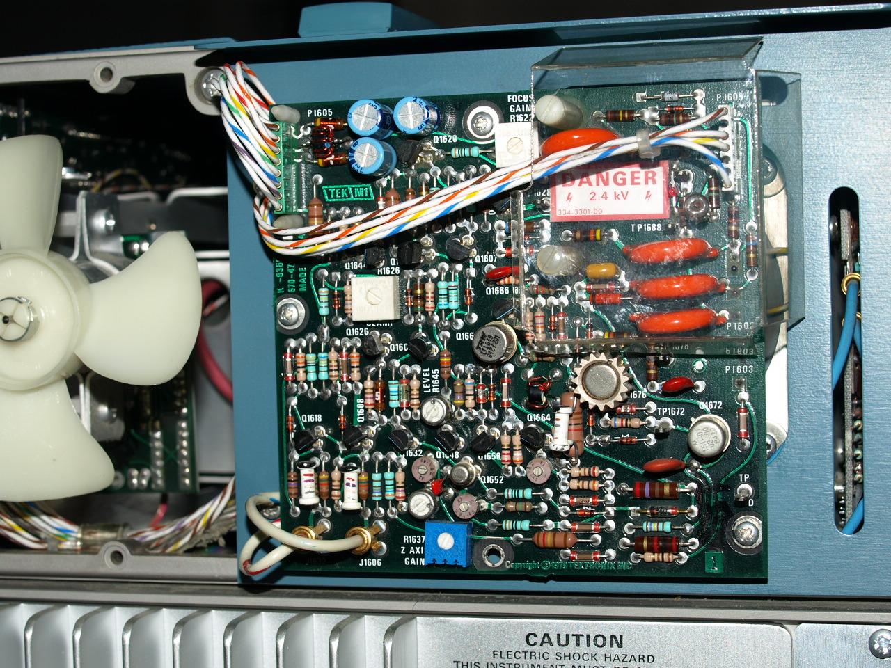
Cleaned amplifier and fan
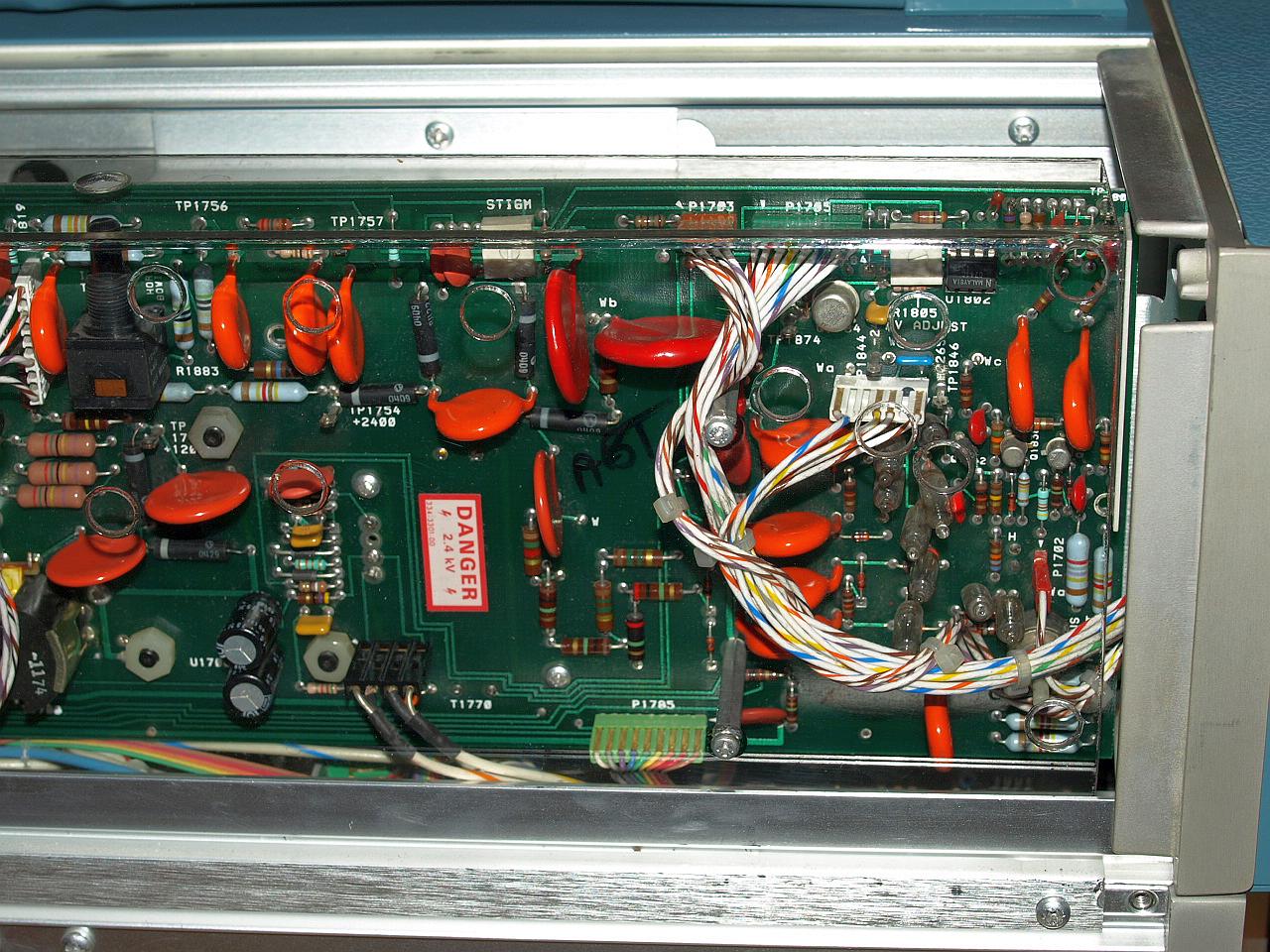
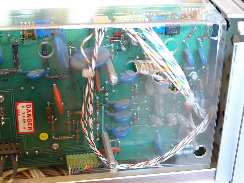
Cleaned High Voltage Compartment
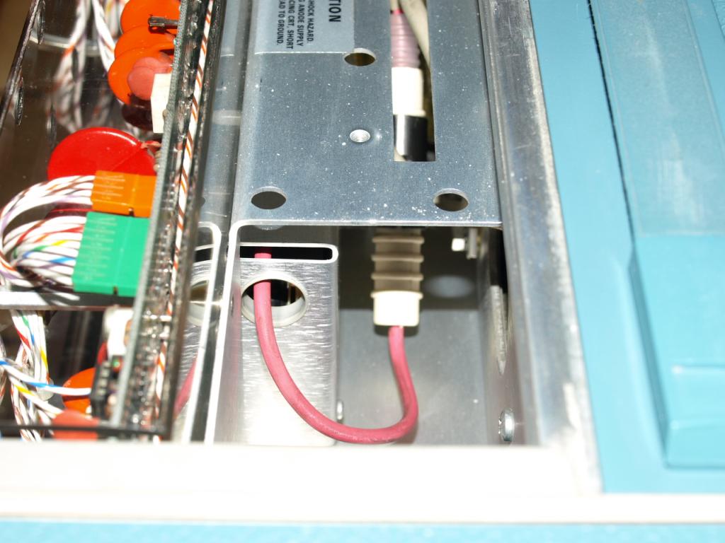
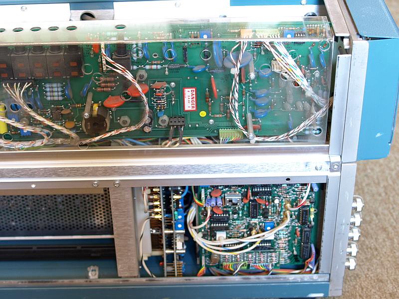
Cleaned High Voltage Cable and Anode Connector
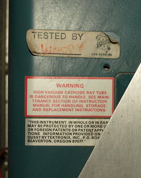
Please follow the
"Caution" instruction on the sticker when removing the high
voltage connector and discharge the anode lead on chassis ground first.
Don't hold the charged anode connector near any electronic part, an
unwanted spark can destroy parts.
Cleaned Instrument.
Be carefull when
cleaning the delicate amplifiers, especially the flexible PCB and wires
near the deflection plates can break easily. Take also care for a
protection against ESD (Electro Static Discharge), in general low
capacitance high speed parts are very sensitive.
| General ESD recommondations when cleaning instruments: |
Reason: |
| Follow standard ESD protection rules
(grounded mates, strap, ESD floors, e.c.t.) |
Save ESD protection |
| If standard ESD protections rules are not
applicable follow steps below: |
|
| clean the instrument being barefooted on a natural unsealed wooden, stone or concrete floor. (Of
course never clean under powered AC-line). |
Less human body charge due walking |
|
Choose damp cotton cleaning rags, not dry synthetics |
Avoid easy chargeable materials, important because they are in direct contact with the IC pins |
|
Avoid any highly isolating materials near the open instrument (plastic, glass, Teflon, plastic tapes and bags e.t.c) |
Avoid easy chargeable materials |
|
Don't walk fast - walk slowly |
Less human body charge due walking, less charge due slower material separation (shoes-floor) |
|
Don't stand up from your chair when touching the instrument |
Avoid human body charge due material seperation (trouser-chair) |
|
Don't use pointed metal objects like screwdrivers or pincettes for
cleaning |
Similar to an lightning arrester, increase electric field strength |
|
Never do it on a day with low air humidity (at least 40-50% relative humidity [under room temperature]) |
Important - dry air increase dramatically chargeable voltages |
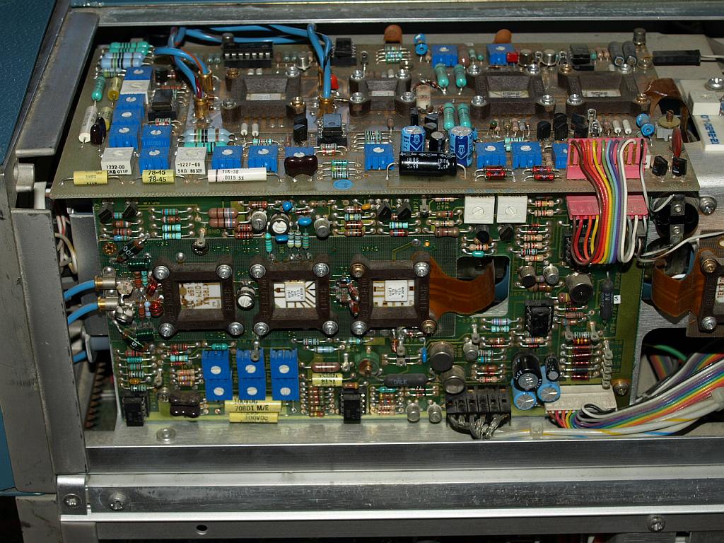
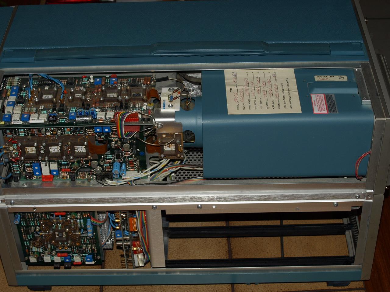
Cleaned Tube Section
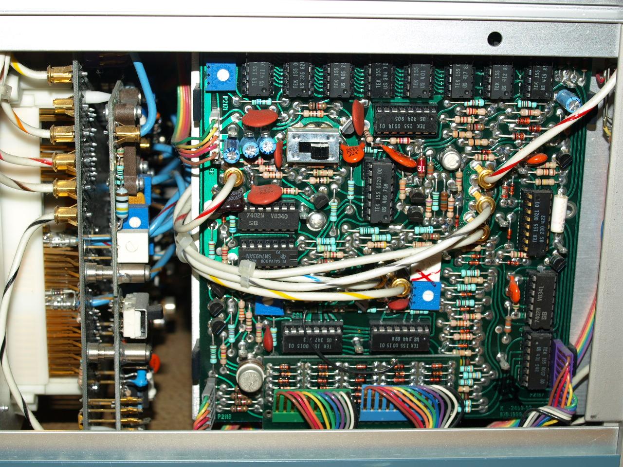
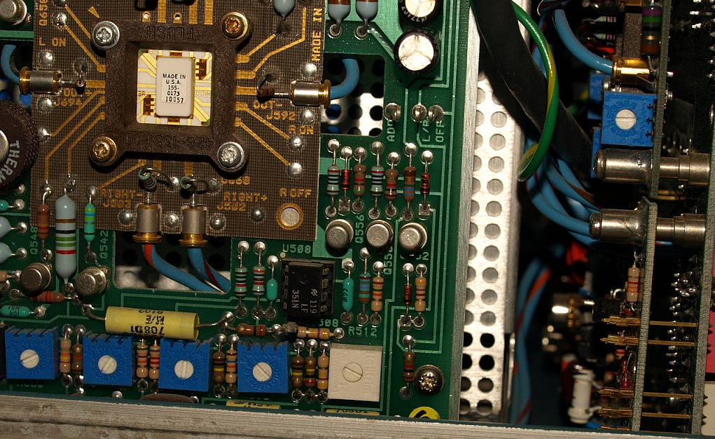
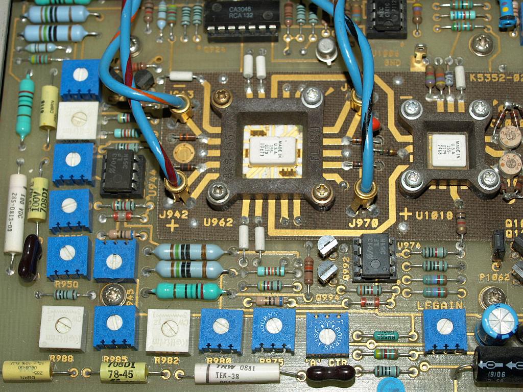
Cleaned Readout Section with a lot of ASIC's.
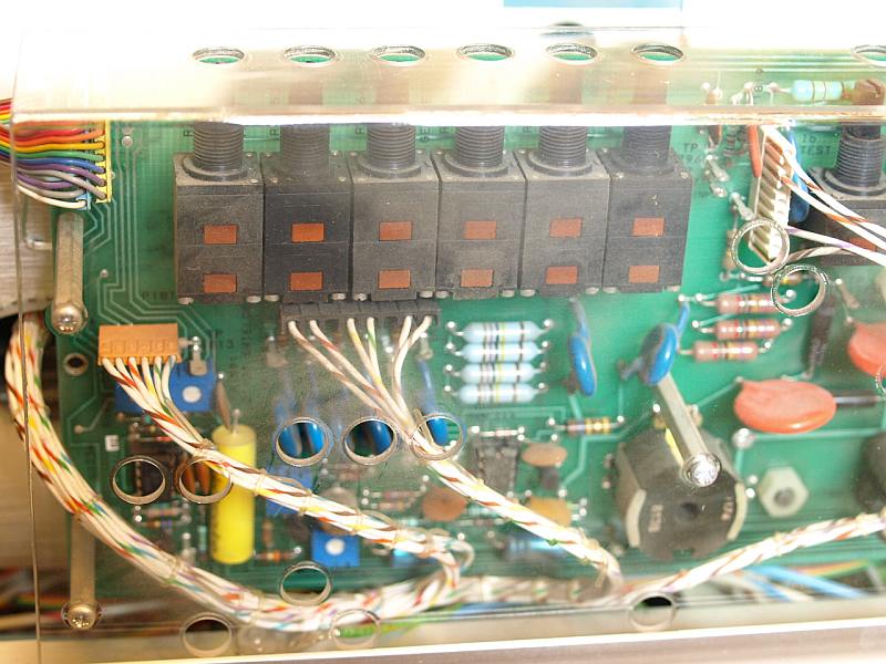
Cleaned Front PCB Section
Cleaned Front Panel
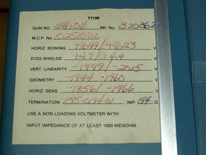
Some minor scratches only, photo flash intensifies them, not visible
under ambient light. Removing all the calibration stickers was a
terrible job and took a lot of time, always being careful not
destroying the surface.
Cleaned Mainframe
Color still powerful and bright,
minor scratches in the surface only. Coaxial connectors still
unoxidized and clean. A carrying handle like new.
Unfortunately the instrument has no options, but this doesn't
matter for almost all applications. If you can buy a working 7104 in
such a condition, don't hesitate to buy and don't care for your money,
this "Peak of Analog Scope Technology" will never come back.
Fourth shown 7104 on this website:
I've got another 7104 in working condition, "buy as is", again I'm a
lucky
guy receiving an 7104 in an almost perfect optical condition.
This time in a seldom full options version ! I've searched a long
time for it.
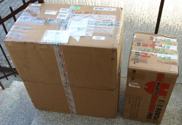
- after unpacking, condition like always: hundred of calibration and property stickers, dusty covers and dirty knobs. -
Receiving some packets on the same
day. This 7104 was ordered overseas, transport costs were higher than
the price for the device. Many electronics don't see the
real value of such an excellent first class analoge scope, they
prefer to pay more money for other (better known) lower
performance second hand scopes and leave such beauties in the shops for
me - thank you -
Some weeks ago a dealer in Germany offered three devices for a
reasonable cheap price, I bought one of them (my third one), his
second one took many weeks before somebody bought it, the third one was
still available lastly. I can really smile, young chick say
sometimes: "this 7000 series is too big for my table and the weight too
much", later they tell: "I've bought a 100 MHz two channel service
scope" (for nearly the same price). Some young electronics have to
learn a lot.
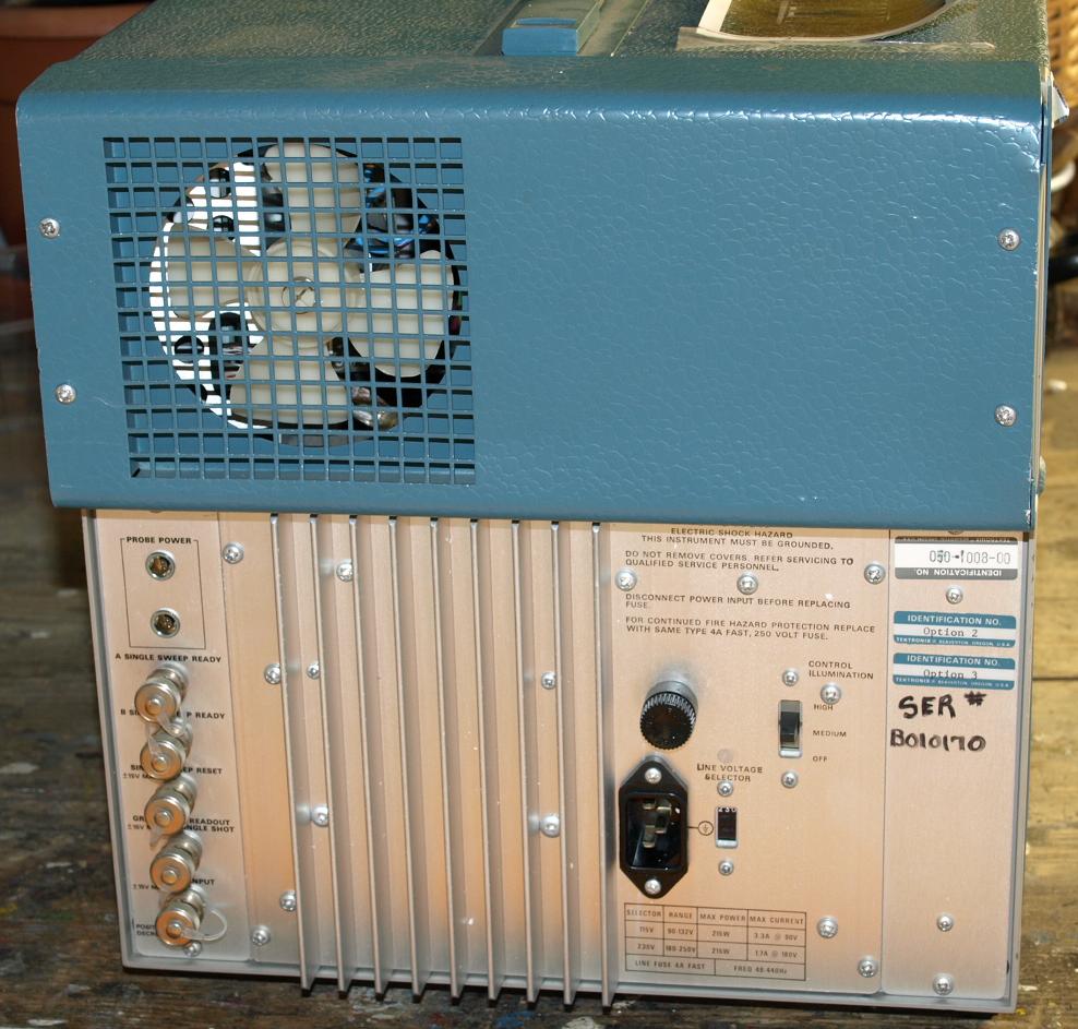
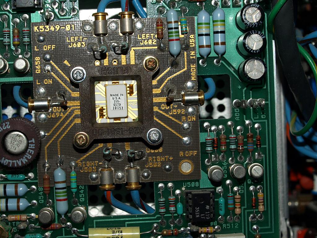
with Option 2 and 3, X-Y phase corrected horizontal amplifier and
improved EMC cover - this type is the peak of analog oscilloscope
development
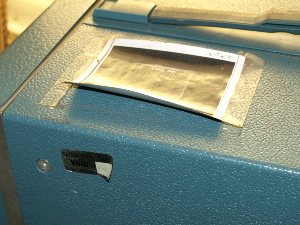
Last calibration in the 90ties from
the manufactorer, somebody put a photo on the cover. I removed the
calibration sticker for an inside inspection check before first time
power on. Always check the correct wired AC voltage before power first
time. The surface is still in excellent condition, only dust.
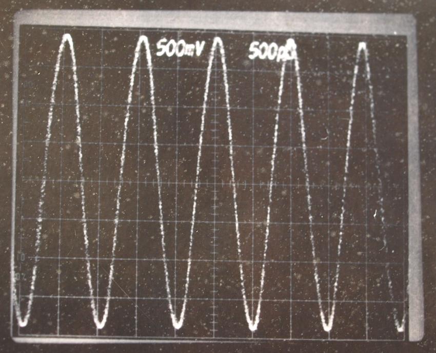
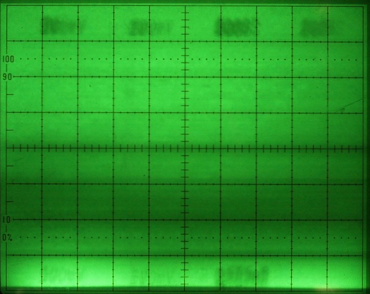
This was a eight division bandwidth test with a 1 GHz signal? - if so, it would be a perfect response. I haven't confirmed.