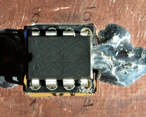
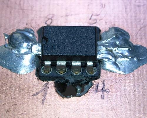
5. Sampling-bridge-driver
Experiments with
different buffers.
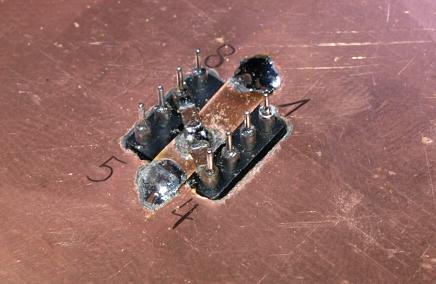
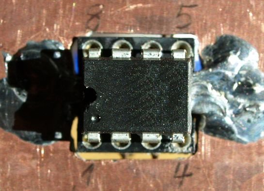
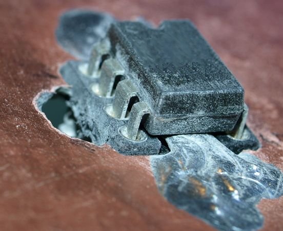
DIP Socket are not good for high frequency, but ok for fast changing
parts.
Drilled and filed. Two X7R capacitors soldered for power supply bypassing.


Top GND plane with a massive connection to the low impedance point.
Some paralled wires, filled with solder.
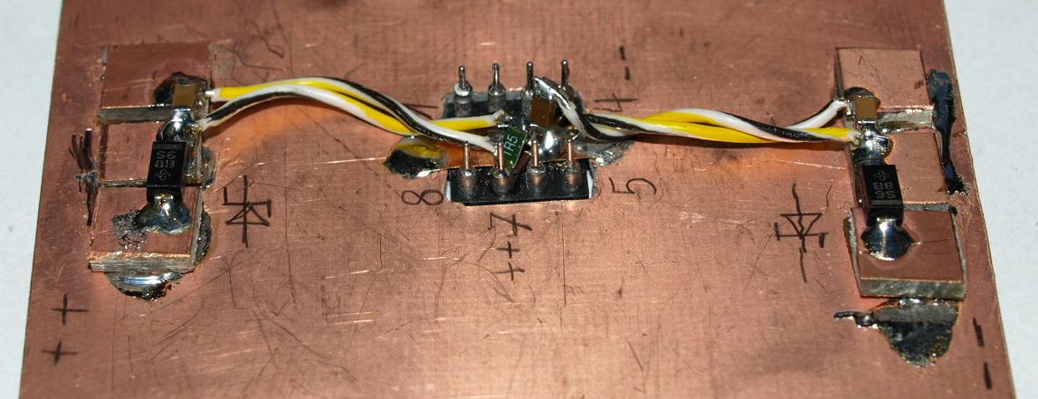
Power Supply with different types of ceramic capacitors soldered direct
on the star-gnd.
Positive and negative supply by wires and polarity
protection schottkys.
It's not my first time doing a mistake plug-in
another IC.
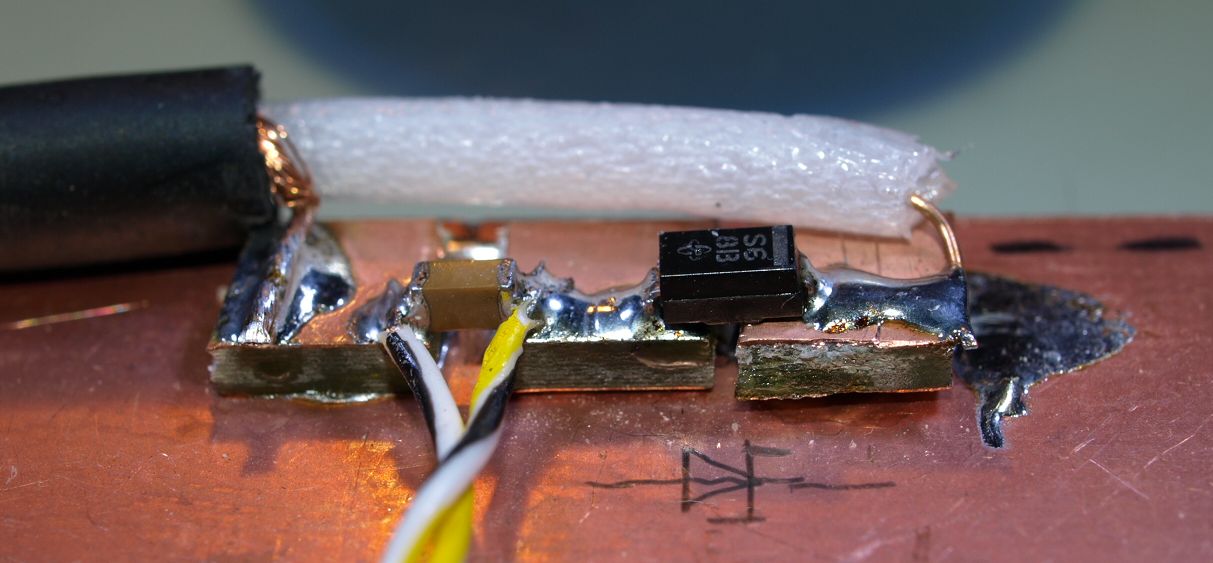
Power comes with a old 75 ohms coaxial cable, series schottky,
4.7µF/25V capacitor X7R as cable buffer.
Small pieces of PCB
as
soldering terminal.

Output PIN 6 a small soldering terminal with a eyelet for the probe.
Power supply bypass with 4.7µF and in series 1.5 ohms with
22nF.
Capacitor grounds soldered to one point.
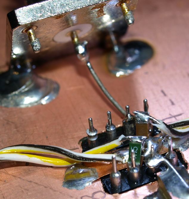
PIN2 non-inverting input coaxial connector.
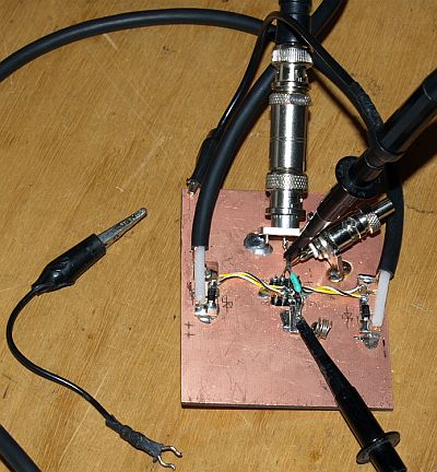
Oscilloscope
used equipment in this experiment :
7A26
vertical amplifier
7904
mainframe
7B92A
time-base
7M13
readout plug-in
1917A
pulse generator

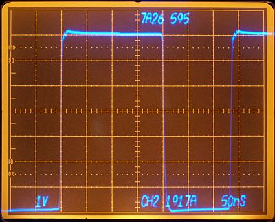
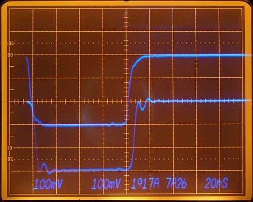
Plug-in amplifiers square wave response from pulse-generator, using a
1:10 probe.
Number 566 and 595 indicates plug-in serial number.
I
choosed from my plug-ins two 7A26 channels showing almost the same
response.
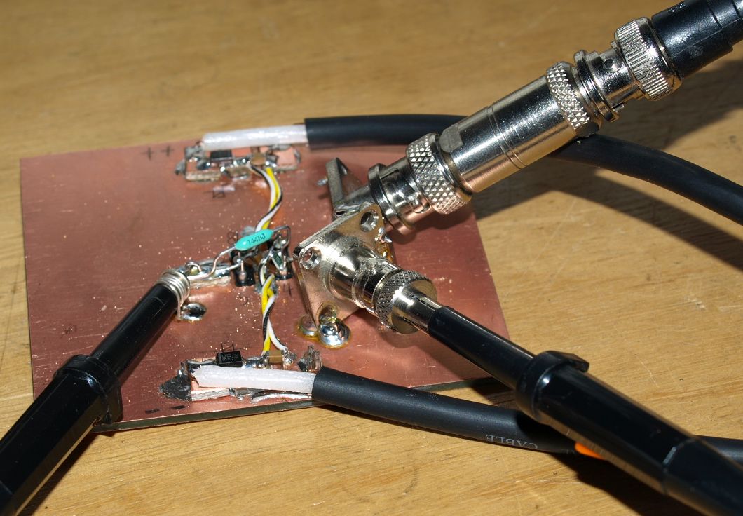
Input and output coaxial.
Input terminated with 50 ohms.
Probes
conncected without alligator crimps.
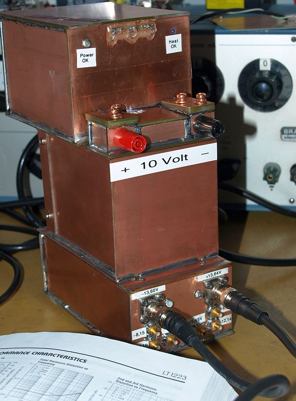
Circuit powered by my transferable 10V reference, including some low
noise power supplies with different output voltages.
Tested OP-amps
I've tried with the fast amplifiers I have in my sample box
at home.
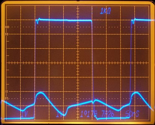
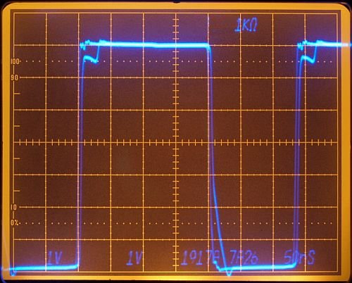
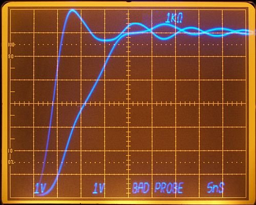
This is a CFA Type xxxx and this type should work with a gain
of Av = +1.
Readout indicates 1kohm CFA feedback resistor Rf.
1917A indicates input signal.
Datasheet specifies for Av=+1 and Rf=750 ohms.
May be the sample don't work. Possible, I've used this sample many
times in the past.


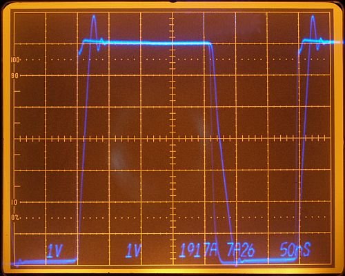
This CFA Type xxxx don't work with Av = +1 gain.
Datasheet do not recommend this amp as non-inverting, large signal
unity gain buffer.
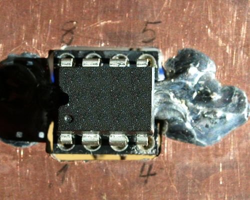

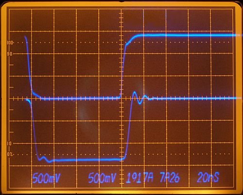
Here a fast VFA Type xxxx with N-jFET input.
Don't
work good with Av =
+1
gain and a fast slewing input.
Using the 1k Rf for a VFA was a mistake.

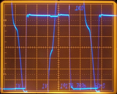
Here a CFA Type xxxx, don't work with Av = +1 gain. Datasheet
do not recommend
non-inverting unity gain with high amplitudes.
Non-inverting input should use a 100 ohms in series (I forgot).
In general many CFA amplifiers work better with a
inverting
configuration with a gain > -1.
Unfortunately a
inverting
configuration would load the settle-node.
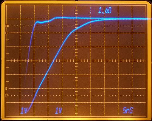
Here a CFA Type xxxx
with very fast slewing.
But I don't like the distorted edge on
the rising slope.
May be some experiements necessary with another Rf
and voltage steps.
Datasheet notes faster settling for inverting gain configuration, a
possible settling problem
for many CFA's?
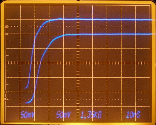
Type xxxx, very good DC specs, low input bias current won't
load settle node much, specified settling time.
Rg=0 ohm

Rising voltage curve of the Type xxxx shows almost a straight line for
small and large signal,
may be this is a key for a good settling time?, also the fast settling Type xxxx comes with a very straight rising
curve.
Some other faster slewing Op amps with exponential rising curve
character having slower settling times!
These are things I want to
discover when the settling time instrument works.


Here a CFA Type xxxx specified for Av = +1, works good.
Faster AC
Specs than Type xxxx, not so good DC-Spec and higher input bias
current.
Responses nice.
Type xxxx vs. probes
and
alligator crimps.
I used the Type xxxx for some experiments with different probe
connections.

Input 50 ohms terminated, porbes using no alligator crimps, output
probe grounded via a self-made ground spring.
Alligator crimps are bad with high frequency signals.
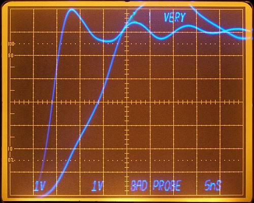
Using only one alligator crimp for two probe makes the disaster perfect.
Layout Improvements
Parasitic capacitance on the input's is bad.
Especially on
the
inverting input a small parasitic capacitance forms small pole at high
frequencies,
resulting in higher overshooting and amplitude response.
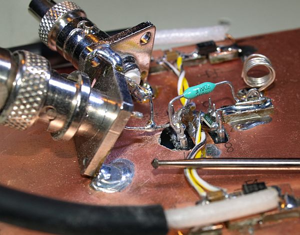
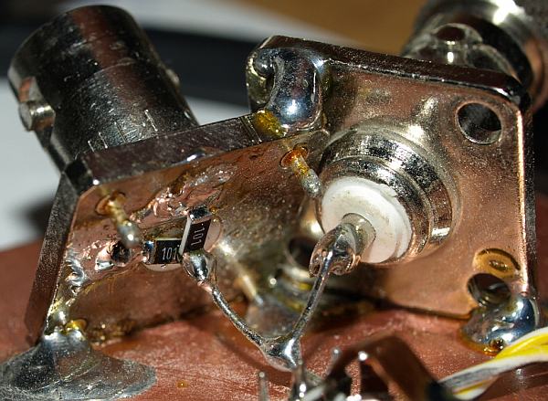
Removing copper around the inputs with a small DIY milling-machine.

Replacing the Dale THT resistor (old military stuff) with a lower
inductance SMD (102) 1000 ohms resistor.
The wide
copper
stripe from PIN6 to the resistor decrease also inductance.
The resistor
is placed close to the inverting input, the low impedance amplifier's
output can easily drive the distance to the resistor.
It's always a
good idea place the resistors very close to inputs and leave the low
impedance signals larger.

Removing the 15cm cable (used before) from the input signal. Direct
connecting to the pulsegenerator's output.
Replacing the 50 ohms terminator resistance by two parallel connected
100 ohms resistors.
In general 100 ohms resistors keep their resistive
behaviour over a wide range of frequencies.
Some commercial 50 ohms
terminators are made of bad quality, e.g. long wires inside - I can't
open mine.
Now the transient 50 ohmcurrent flows a little closer to the clean
analog circuit ground
- it can be dangerous -
fast transient current
spread wide inside the ground plane.
There are also some notes in the
AN-74 about this problem.

Input signal got a small piece of cooper reducing inductance.
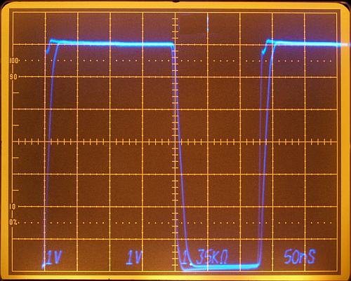
Comparison of Layout
improvements
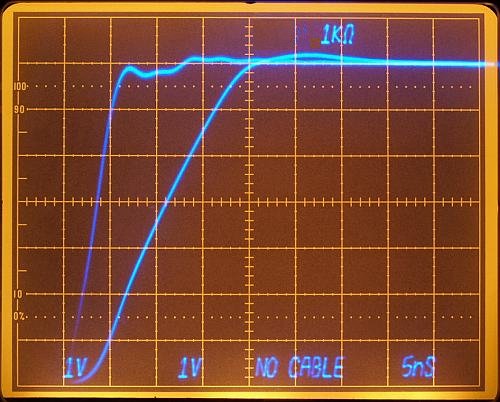
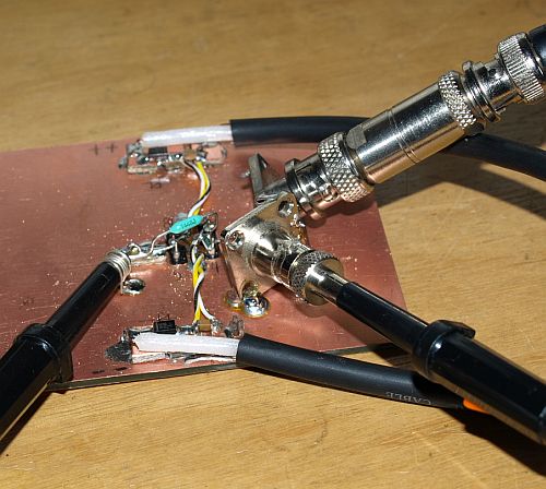
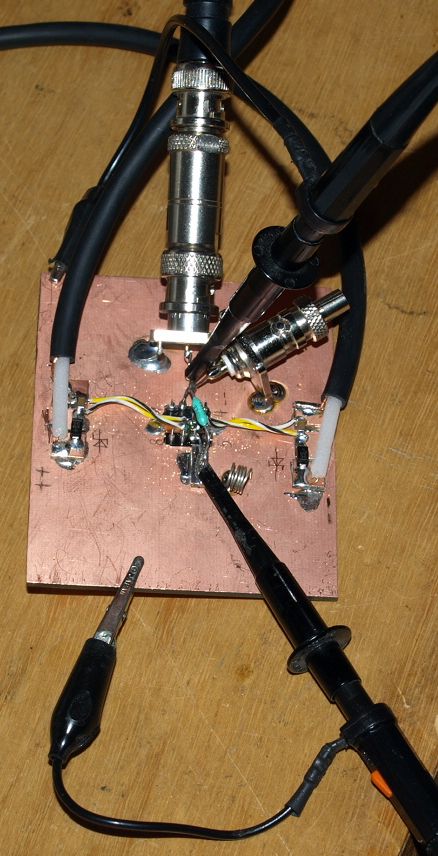
Photo A (left) like before with 15cm cable. Photo B (right), inputs
with reduced parasitic capacitance.
Lower feedback inductance and
without cable direct on pulse-generator,
decreased ringing. Removing
the cable showed the most influence.
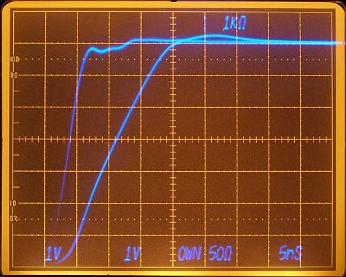
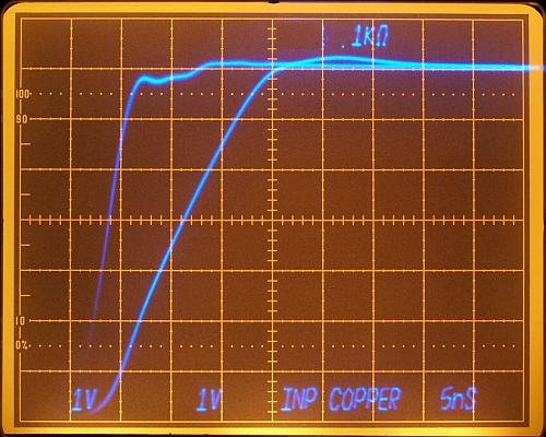
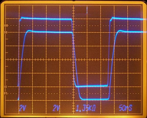
Photo C (left) without cable and with selfmade 50 ohms termination
better than photo B, shows less ringing.
Photo D (right) with small
copper on the input - no change in performance.
CFA vs. different Rf
The ideal CFA has a bandwidth independend from closed loop
gain over a wide range of loop gains.
Bandwidth changes also
with Rf.
Experiments with
decreasing Rf:
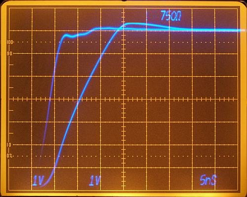
Rf = 1000 ohms
Rf = 750 ohms
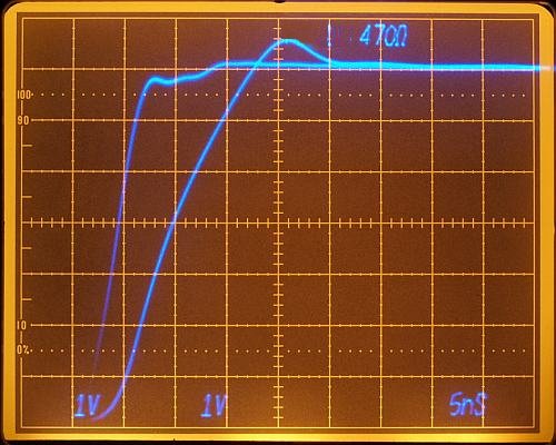

Rf = 470 ohms
Rf = 300 ohms
Decreasing Rf increases bandwidth and slew rate but but also
overshooting and ringing.
Experiments with
increasing Rf:
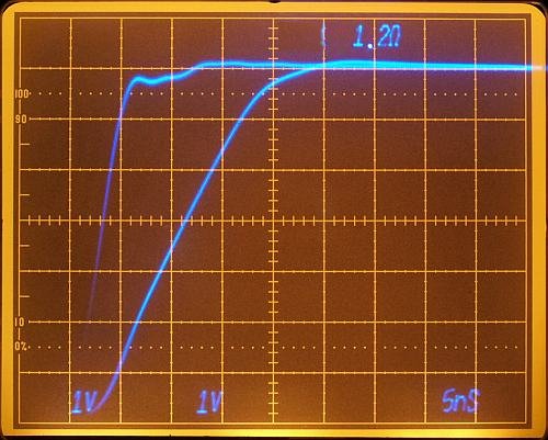
Rf = 1200 ohms
Rf =
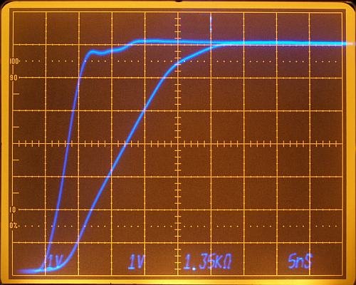
1350 ohms
Rf = 1600 ohms
I choosed Rf = 1350
ohms for further experiments:
Rf=1350 ohms is a good
choice for starting, seems a very little overdamped with 1k35, no
problem.
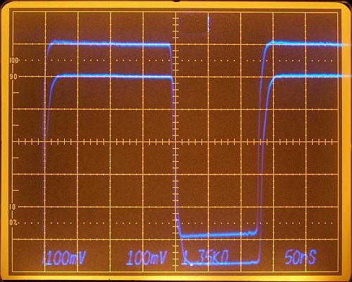
Type xxxx vs.
capacitive
load

Ceramic capacitors close on the output.
The 1350 ohms are
paralled by two 2700 ohms.


1nF 200mV step
10nF 200mV step


10nF 6V step
10nF 10V step
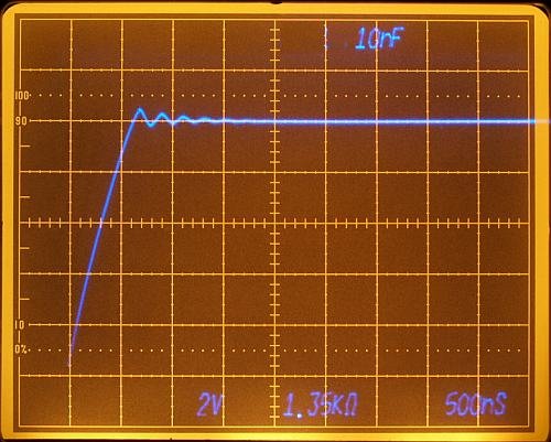
10nF 10V step
I don't know how these amplifiers work as sampling-bridge-driver, we
will see. Makes fun to evaluate all this things.
There are
many question on my list to
discover, this settling time test equipment will be a very
powerfull tool to see all these hidden things.