17. Trigger Generator Assembly Part Two


Describes the Square Wave Generation and Measurement Path Compensation.


First DELAY TIME Test


Delay Time adjustable from 14 ns to 50 ns.

At the moment bad probing for the input channel, termination is not optimized and results in high overshooting.
This fast CMOS Inverter slews in some nanoseconds.


Termination of Digital Signals


The two potentiometer are an adjustable source-series-resistor to reject the reflected wave coming back from the open line end.


A simple series resistor in the range of 50 to 100 ohms improves the signal at the BNC Terminals.
The loss of slew rate is acceptable, a compromise of speed and overshooting.


Digital Compartment (bottom) and Measurement Compartment (top) soldered together as "one piece".
A better more low inductance ground for all signals. Maintenance for the digital part remain easy from the bottom side.


Different Types of Signal Termination


An unwanted problem with fast digital and high frequency signals.

Every impedance change for a travelling wave along it's way will cause an reflected wave. The reflected voltage wave form, polarity and their wave currents depending on the impedance along the way. The measured voltage depends not only on time, also on location. Only a equal impedance won't change the waveform characterics, but the amplitude decreases along it's way to the receiving element.

Source Impedance = Transmission Line Impedance = Load Impedance

The basic mathematic equations are not difficult for travelling waves on a line, but to understand it in the reality is much more difficult.


General:

  • Measure the receiving and sending gates with a good low capacitance active FET Probe, for example a Tektronix P6201, with a low inductance ground spring mounted direct on top of the probe tip. Even the slower 7A11 amplifier plug-in is a very good choice for such a measurement. Of course on the Scope Trigger Input the measurement and adjustment should be done direct on amplifier you are planing to trigger.
  • A fast slewing signal is very good for trigger stability and a secure trigger. Especially the fast logic devices demand for high input slew rates, with slow rising noisy inputs they can oscillate. or ring. An input signal with a big jitter should be at least fast to trigger save. In the midrange trigger voltage range the input signal must be steep, above these area the input signal can have a reduced slew rate. Adjust the series resistor for a good compromise between all.
  • Place SMB and BNC connectors close as possible to the sending and receiving element. Changing from a simple cooper wire to a BNC connector is a impedance change and this cause reflections. The close terminal placement near the gates reduce also the current loop within the ground plane.
  • For internal connections may be striplines with a higher Zo impedance would be a choice, but without reading a book I 'am not able to calculate them at the moment.


Some Series Resistor Termination Examples


Time corrected input signal for triggering the oscilloscope with a bad termination - fast extreme


The bottom 5V signal comes out from the Hex CMOS Inverter with an appr. 10 ohms series resistor directly on the inverter output. The settling-time-instrument is connected with a 40cm RG-58CU 50 ohms cable to the 1Mohm/20pF input of a Tektronix 7A26 Vertical Amplifier with 200 MHz bandwidth in a 7904. The reflected wave comes back from the oscilloscope causing a high ringing with about 3 volts overshooting. The slew rate of the rising edge is very fast with this capacitve load (cable+1Mohm/20pF) and a medium speed 200 MHz 7A26. The wiper of the series resistor potentiometer was almost in zero position (I haven't measure it). With the wiper in zero position, the overshoot reaches almost 4 volts ! The gated-settling-time trace measured with a second 7A26 amplifier in it's 20 MHz position.

The top trace is the gated-settling-time window with 500µV/DIV on the settle node. This trace is displayed here for information only to observe if a series resistor adjustment will cause a changed waveform of the DAC amplifier, fortunately I could not see any changes in waveform.

The timing information between both traces is not correct, because both traces were triggered with two time-base Plug-In's 7B85 and 7B80. The 5V trace has been moved horizontal to the right side of the CRT to show better the rising edge.


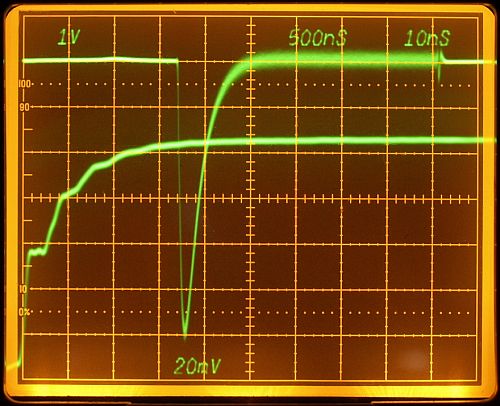
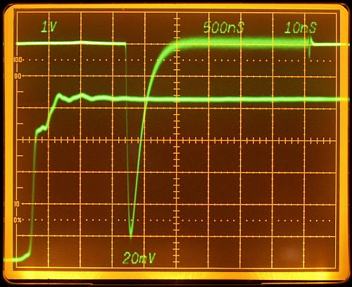
Time corrected input signal with a bad termination - slow extreme.


Same conditions as decribes above, but with an increased series resistors of some hundred ohms. This takes high frequency contents away and decrease slew rate. Such a waveform is dangerous, because the rising edge is very distorted. In the worthwile midrange of the slope there is a small flat "shoulder" area, triggering in this area would cause increased jitter and a fast logic device could even start with oscillations or ringing. The good thing in this experiment, the waveform of the gated-settling-time has not changed.


Time corrected input signal with a trimmed termination.

Potentiometer trimmed to 53 ohms, resulting in an undistorted rising slope (within 0V to 4V) - less overshooting - oscilloscope will trigger save.


   Digital Signals with Trimmed Termination


Photos always showing the rising and falling edge.

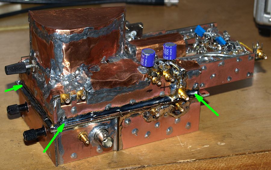
All measurements done with a 7904, 7A26, 7B85, 7B80 and a good quality 1:10 passive probe with a low inductance GND spring on the tip.


Time Corrected Input Signal - 53 ohms

(exception - using a 40 cm coax cable instead of the probe tip).


Window generator input, using a 88 ohms series resistor. Nice waveform - device will trigger save.


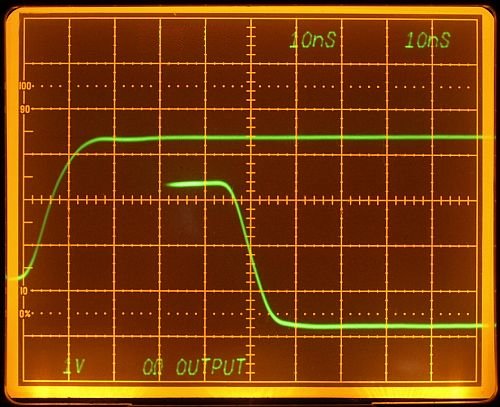
Window generator output, using a zero ohms series resistor. Nice waveform - diode bridge will switch save.

No series resistor was the best choice here.
The falling edge switch the HF transistors in the diode brigde.
Signal is steep, undistorted and fast.


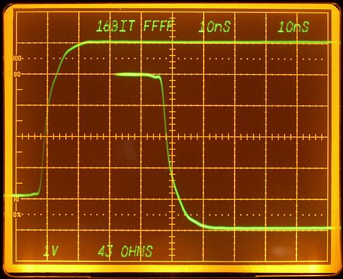
Load DAC and all 16 Bit signals for FFFF full scale step - looks good.

43 ohms series resistor.


"Even digital electronic can be interesting to explore, when you keep on thinking analog".


back


Impressum und Haftungsausschluss