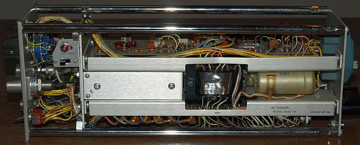
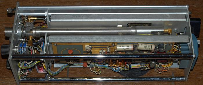
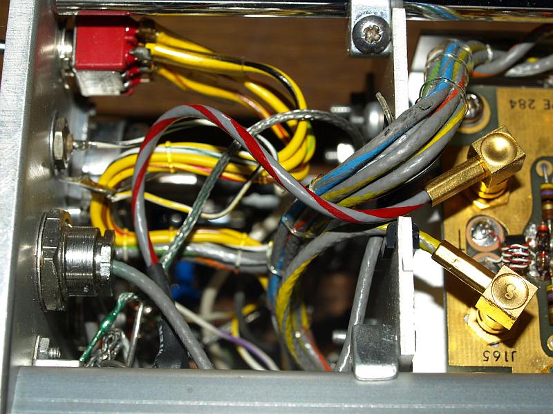
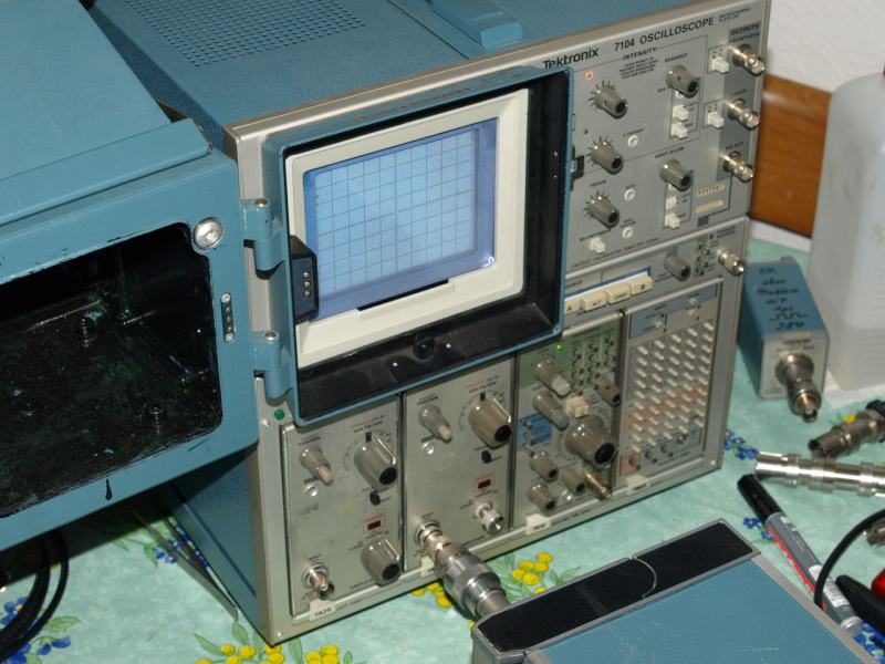
Very simple construction to reach all parts when reparing or service.
Takes not more than 10 seconds to slide out the Plug-In.
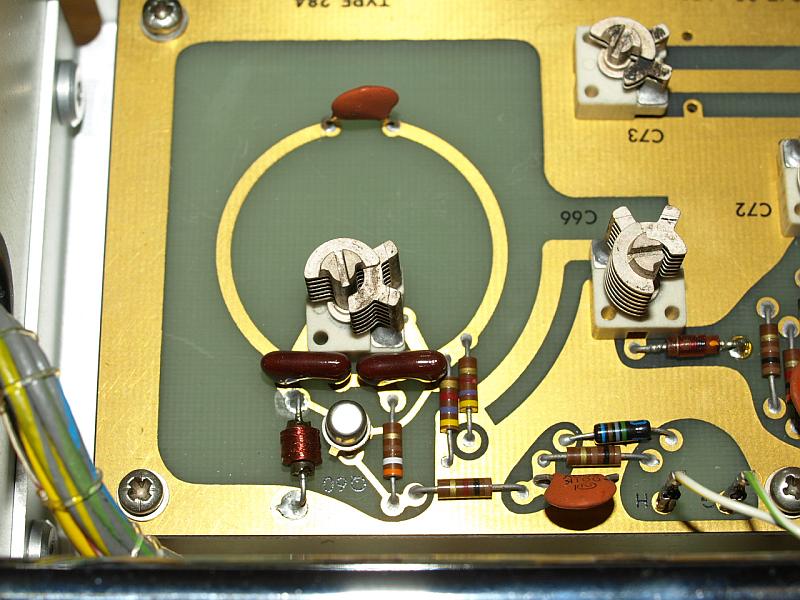
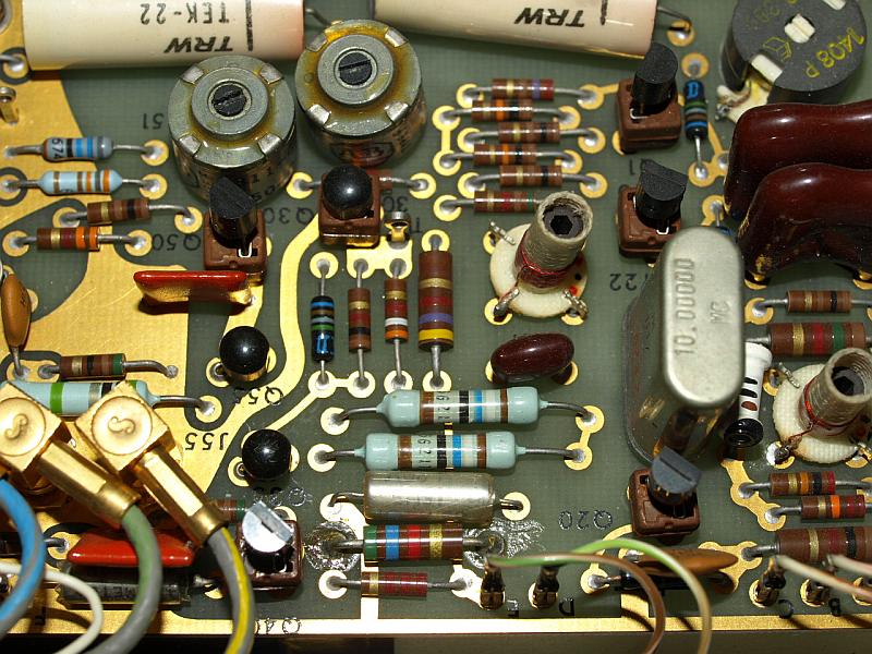
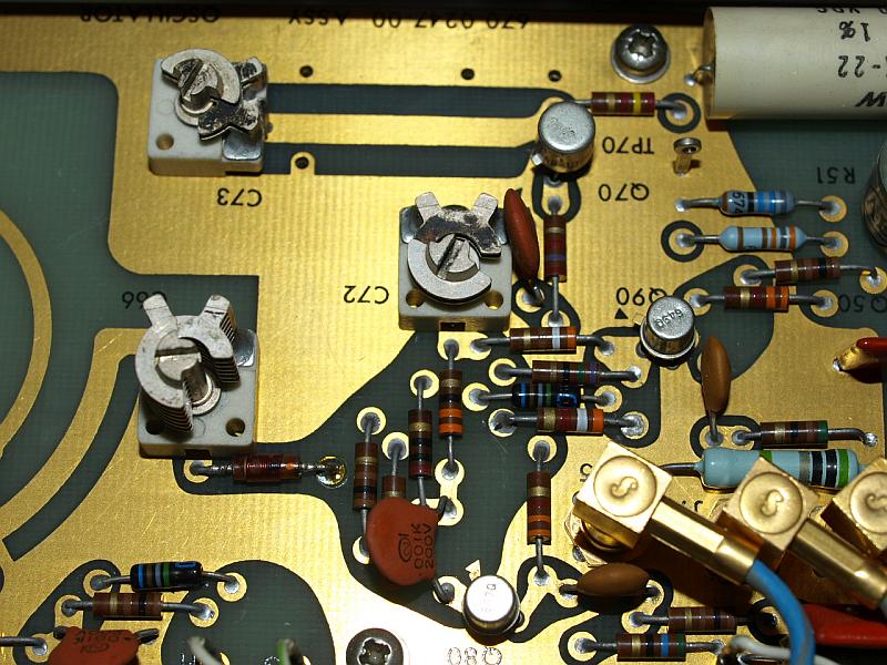
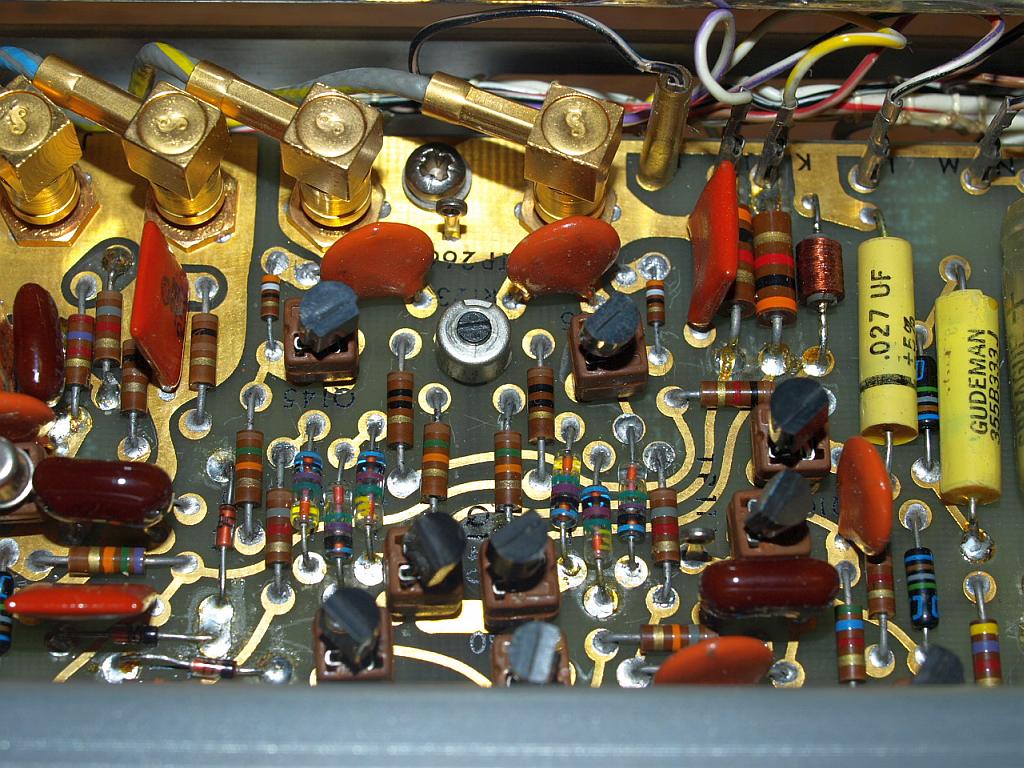
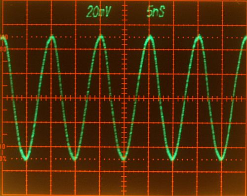
Amazing layout in the sine generator
Quartz and LC controlled oscillators
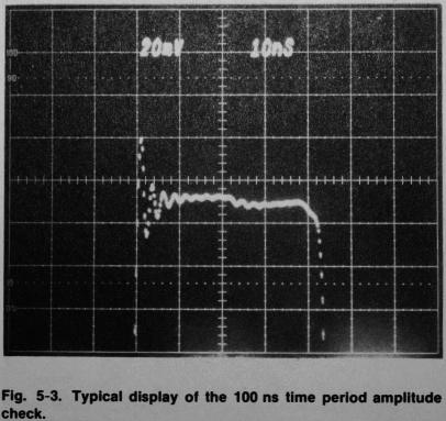
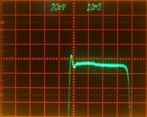
1ns and 10ns Timing Adjustment
|
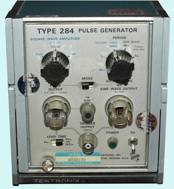
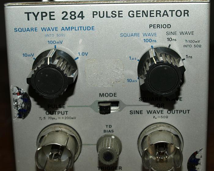
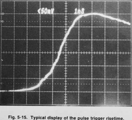
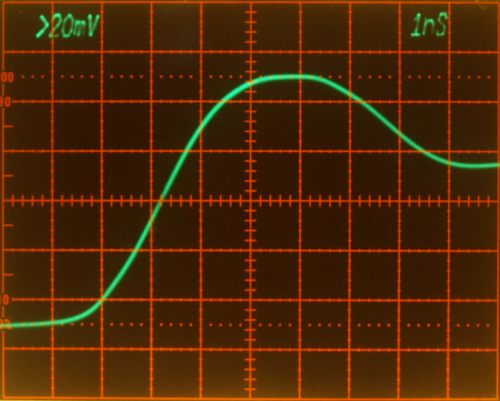
The Tektronix Type
284
is a very fast
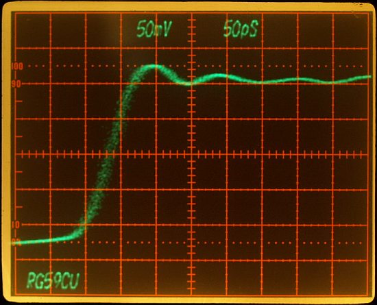
Pulse Generator and comes with a risetime of <=70ps
with 50 kHz
repetition rate. This repetition rate is high enough for a clear
display on oscilloscopes, compared to the approx. low 700 Hz
repetition rate of the Type 109
mercury relais pulse generator a big advantage.
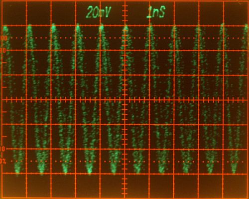
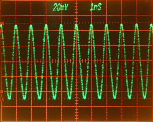
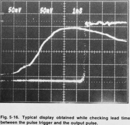
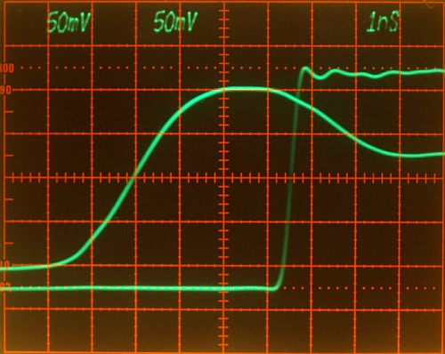
The instrument is fast enough for testing Sampling Oscilloscopes or vertical amplifier risetime. Another application are fast pulse in Time Domain Reflectometry or any general purpose risetime measurement. The second output has either a square-wave or sine-wave output. Square Wave: 100 kHz, 1 MHz and 10 MHz with a 50% Duty Cycle and 1V, 100mV and 10mV amplitude into 50 ohms. Sine Wave: 100 MHz and 1 GHz with a 100mV amplitude into 50 ohms. Pulse Amplitude: >=+200mV Low Pulse Flatness <=3%p-p within the first 2ns. Pretrigger capability. The Service Manual has a lot of useful information about this instrument and application hints, it's really worth to search for it. This instrument is seldom available. Sometimes it is selled cheap on second hand markets, but in most cases the price is high. There are not many generators available with such fast risetimes. Unfortunately the shown instrument don't work, it has a fault in the power supply and will be repaired during wintertime. |
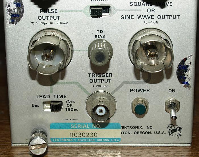
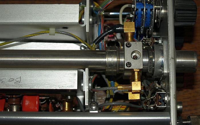
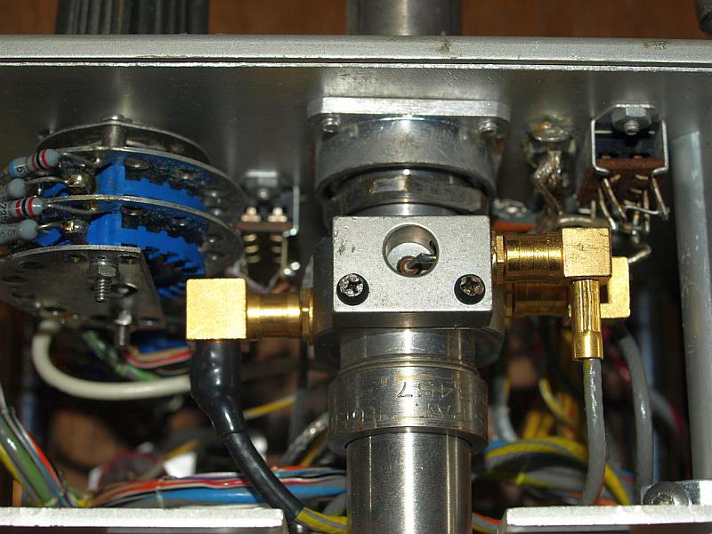
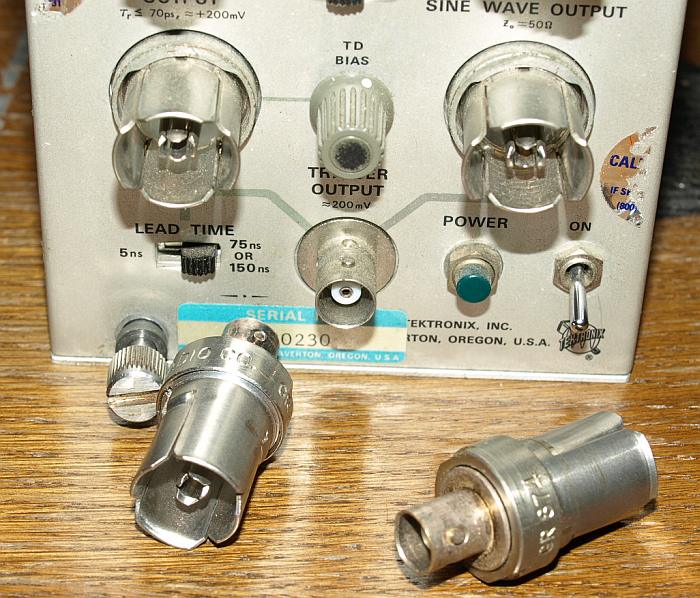
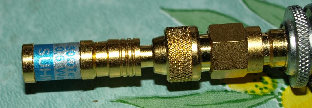
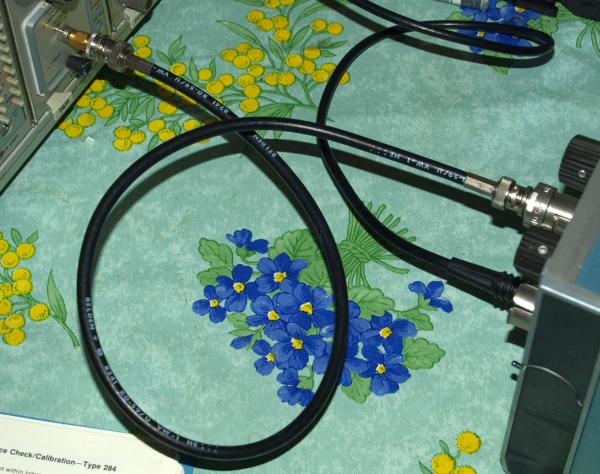
| Als Ausgang verwendet dieser Generator noch das GR-874 system, neben
den guten elektrischen Eigenschaften zeichnet es sich aus, dass dieser
Steckertyp keine Buchsen und Stecker kennt, jede der Verbindungen kann
beides gleichzeitig sein, einfach um 90° verdrehen und aus Buchse wird
Stecker und umgekehrt. Leider ist dieser Typ nicht mehr aktuell an Messgeräten zu finden. Outputs came with General Radio GR-874 connectors, which are unfortunately no more build. |
|
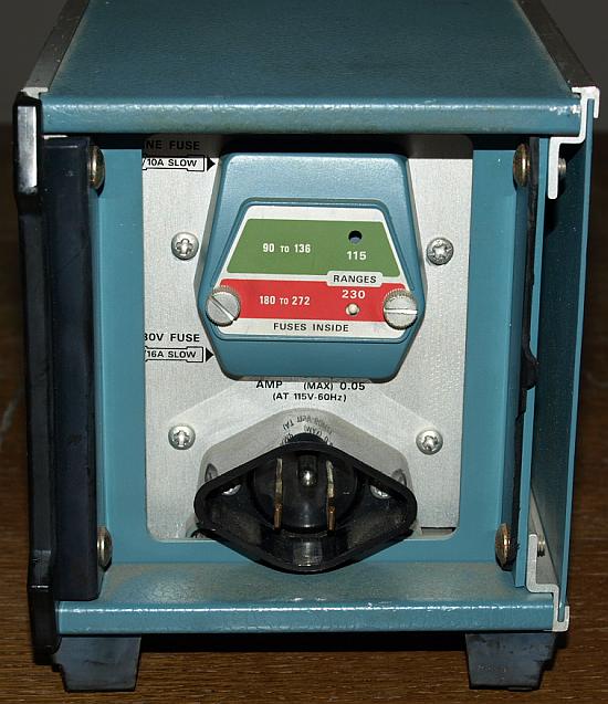
Why the instrument worked
under 115V and not with 230V ?
Im 230V Modus ging gar nichts,
da eine der in serie geschalteten Wicklungen unterbrochen war, es
fließt durch beide Wicklungen kein Strom, daher auch kein
magnetisches Feld an den Sekundärwicklungen. Im 115V Modus
hingegen liegt eine der beiden Wicklungen an Spannung und daher unter
Stromfluß. Bei 115V wird das Gerät nur aus einer Wicklung
versorgt, bei der geringen Leistungsaufnahme und der Dimensionierung
funktioniert das Gerät trotzdem.
In the 230V mode are both transformer windings in series, with a broken winding, no current can flow. In the 115V mode are both transformer windings parallel connected, if one winding broken, in the other still current flows. The instrument has 6 watts and worked with one primary winding only, the secondary voltage was high enough. |
|
Diese kleine Drahtbücke wieder am alten Draht anzuflicken war
wieder eine Fummelei und Strafarbeit. Schwer zugänglich und ultrakurz, nicht mal richtig
fotografieren konnte man es, aber es hält.
It was a hard work to resolder the broken transformer wire again, luck that it was not necessary to remove the transformer. Fault 2:Im Pulse Modus war die Ausgangsamplitude unstabil, es roch schon
förmlich nach einem Wackelkontakt, der überall sein konnte. Manchmal
blieb die Amplitude für Minuten stabil, dann wieder chaotisches Verhalten. Der
Fehler sah so aus, dass die höchsten Frequenzanteile noch gut
übertragen wurden, die etwas niederfrequenteren jedoch gedämpft, das
sieht dann so aus wie bei der 1:10 Tastkopf Kompensation wenn bei falscher Einstellung der Peak nach oben schießt.
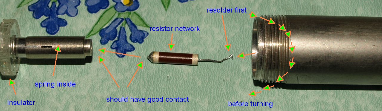
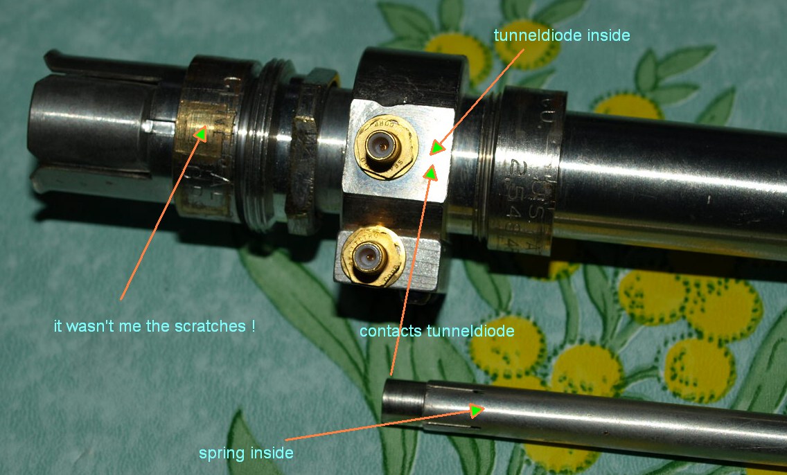
An mehreren Stellen nach dem Fehler gesucht, letztendlich zur Erkentniss gelangt der Fehler muss irgendwo innerhalb der Tunneldioden Luftleitung liegen. Feststellen lies sich das durch gezieltes Klopfen mit einem Schraubenzieher, aber es dauert ein wenig bis man lernte es gezielt zu provozieren. The pulse mode had an unstable output amplitude and a high frequency error. In some Time/Div settings, highest frequencies were passed, some lower frequencies didn't passed, looked like an overcompensated X10 passive probe. Sometimes after knocking on the device, the amplitude jumped to a reasonable value - sometimes after knocking the amplitude was wrong again. I tried many things to find the error, it could be a bad soldering, an internal broken part or just a bad connector. After locating the place of error by knocking with a small metall srcewdriver I could locate the fault. Something must be wrong inside the tunneldiode airline. |
|
|
Alle Kontaktoberflächen wurden gereinigt und mit Alkohol gereinigt,
anschließend mit einem Kontaktöl gegen zukünftige Oxidation ein wenig
geschützt. Der Widerstand bekam auf der linken Seite etwas neues
Lötzinn als Kontaktfläche, das alte sah schon irgendwie etwas
mitgenommen aus. Pass bloß auf diesen Widerstand auf und mach ihn nicht kaputt.
I cleaned all contact surfaces and put some contact oil for protection. I put a litte bit new solder on the left side of the resistor, I didn't trust that old contact. Be careful with this resistor. |
|
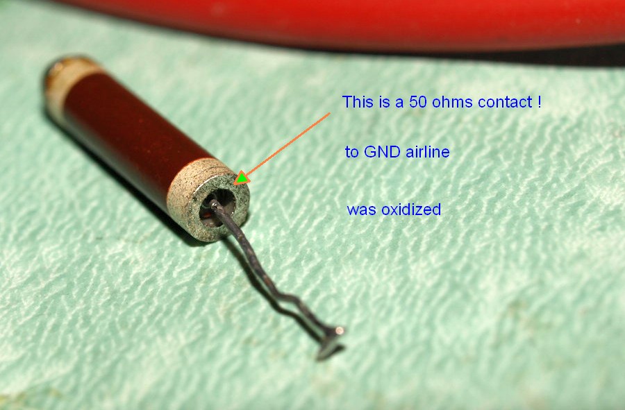
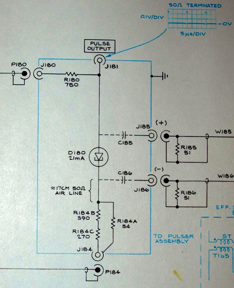
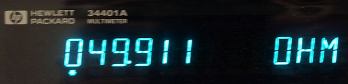
Dies ist ein 54 Ohm
Spezialwiderstand bestehend aus dem Netzwerk R184A, R184B und R184C in
einem Bauteil ! Die gezeigte Kontaktfläche gehört zum R184A
und bildet die Masseverbindung zur Luftleitung, dieser Kontaktbereich
war stark oxidiert, schon richtig halbschwarz, vermutlich war das die
Ursache für die schlechte Verbindung. Sei vorsichtig mit der Arbeit
an diesem Widerstand, wer den kaputt macht, der steht garantiert vor einem gewaltigen Ersatzteilproblem.
|
 |
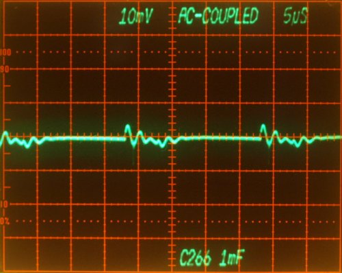 |
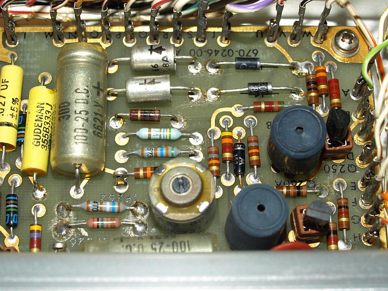
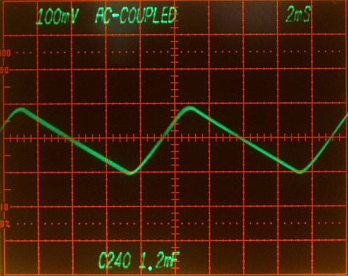
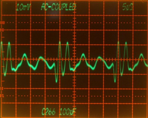
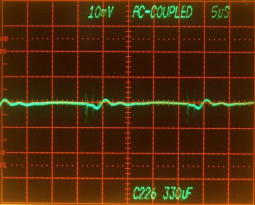
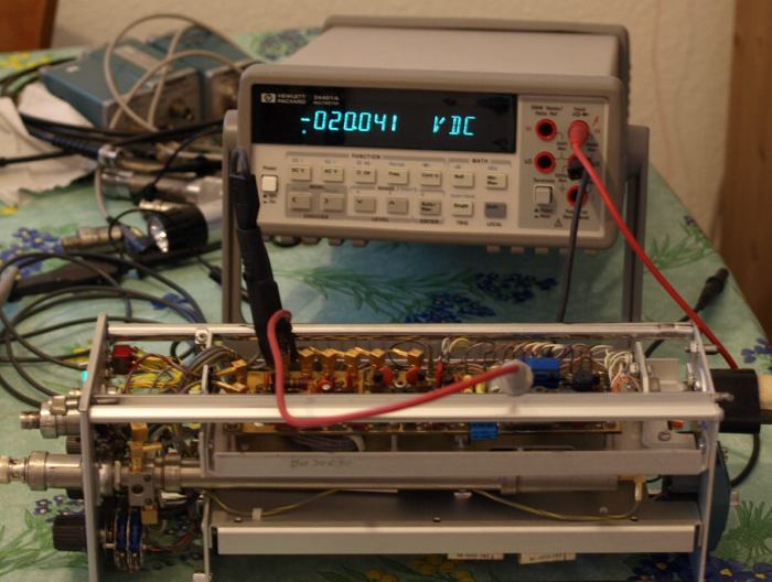
| C266,
100µF Electrolytic Capacitor on the regulated -20V supply The spikes and ripple caused by the the 50 kHz pulse mode, there is no 100 Hz Ripple observable, rejected by regulator. |
C266 and an paralleled 1000µF capacitor. Additional C reduced the remaing switching ripple. |
 |
 |
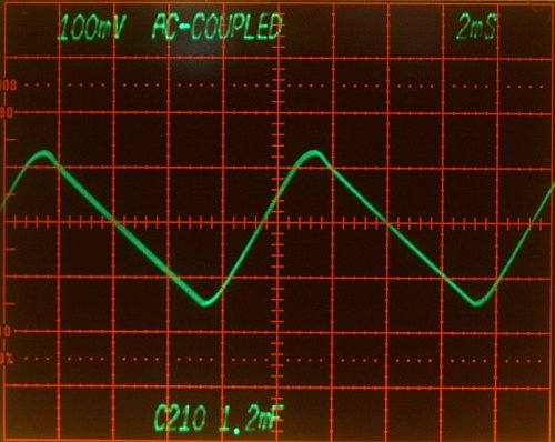
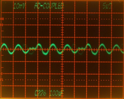
| C226,
100µF Electrolytic Capacitor on the regulated +20V supply The spikes and ripple comes from the 50 kHz pulse mode, there is no 100 Hz Ripple observable. |
C226 and an paralleled 220µF capacitor. Additional C reduced the remaing switching ripple. |
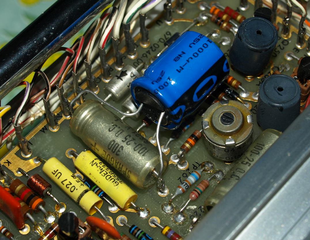
Der Spannungsregler kann die 100 Hertz Brummspannung in exzellenter Art und Weise unterdrücken, auf dem Oszilloskop ist nichts mehr davon zu sehen. Bei den hohen Frequenzen streicht er allerdings die Segel und unterdrückt nur noch gedämpft. Ich habe als Parallelschaltung zu den alten Elkos noch Folienkondensatoren ausgetestet, deren niedriger Ersatzserienwiderstand ist keine so gute Idee, der Spannungsregler antwortete prompt mit einer kleinen Oszillation, auf eine Vergrößerung der Kapazität mit Elkos reagierte er angenehm. The voltage regulator rejects the 100 Hz noise excellent, but the regulators can't reject the fast transient loads in the same way as the 100 Hz. These added electrolytics improved the supply. I tried also low ESR foil capacitors in parallel, the regulators started to oscillate with them. |
|
|
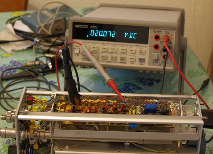
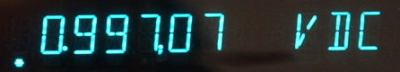
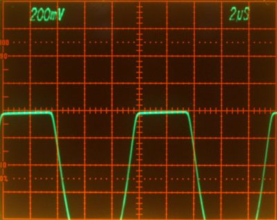
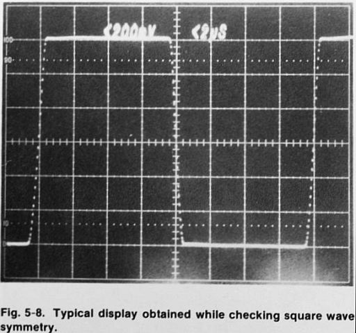
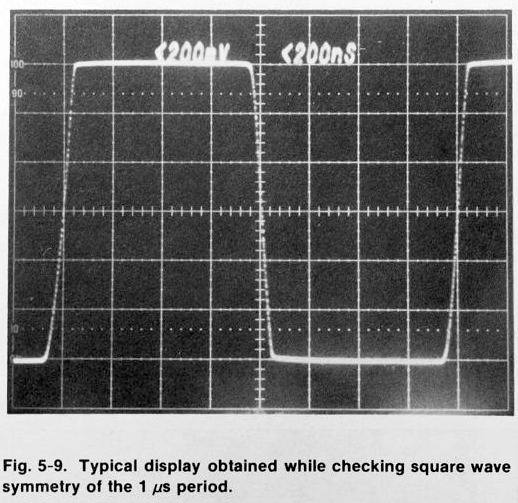
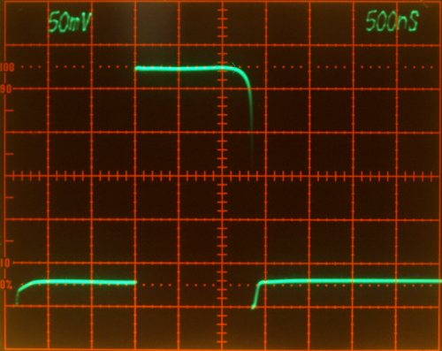
Put back transistor Q35 in its sockets, the square wave appears on the
CRT. The flat shoulder of the square wave should not move away from the
former beam position (when DC), movement should be within 20mV.
Failed
Ein blöder Fehler, die Reduzierung der Amplitude beim Schaltvorgang ist etwas höher als erlaubt. Wahrscheinlich ist irgendwo ein Signalpfad zu hochohmig, mag es der Transistor oder eine Steckverbindung sein. Ist allerdings nicht so wichtig, der Rechteckgenerator hat außer der Frequenz nichts mit dem Pulsgenerator zu tun, und genau den benötige ich. Irgendwann mal ist dieser Fehler fällig. |
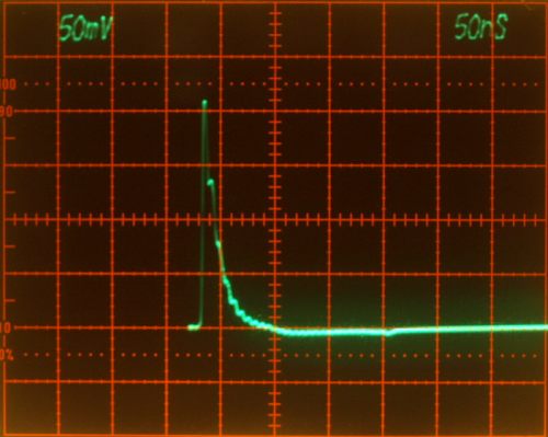
| Das
sieht verdammt aus nach einem erhöhten Widerstand innerhalb des
Signalpfades, was auch den Anstieg der Flankenzeit erklären
würde, da
der Widerstand zusammen mit einer Kapazität am Ausgang eine RC
Zeitkonstante bildet, die bei größerem R länger zum
einschwingen
braucht und die Anstiegszeit verlängert. Rise- and Falltime to slow, don't know why, may be the same fault as in step 4? Increased RC ? |

1. Test |
2. Test |
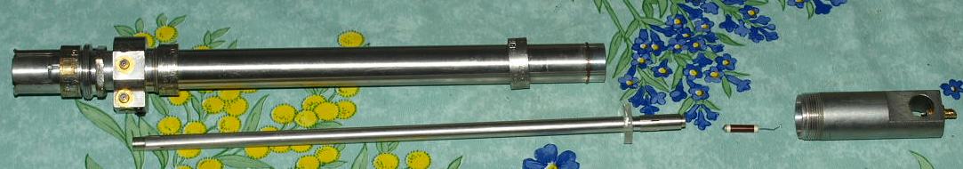
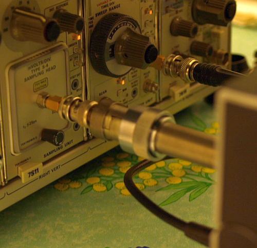
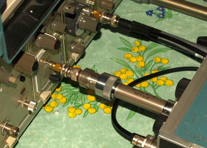
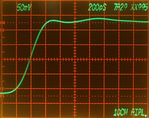
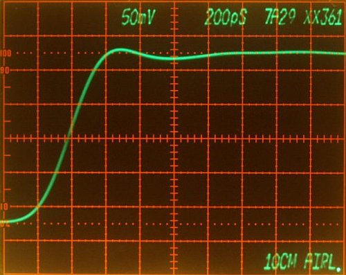
 Using a S-4
Sampling Head (tr <= 25ps)
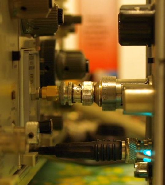
Two adapters only, shortest possible connection.
|
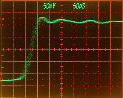
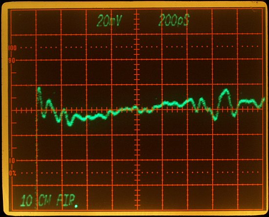
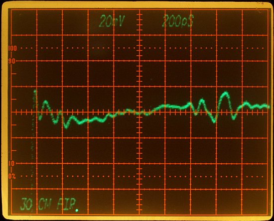
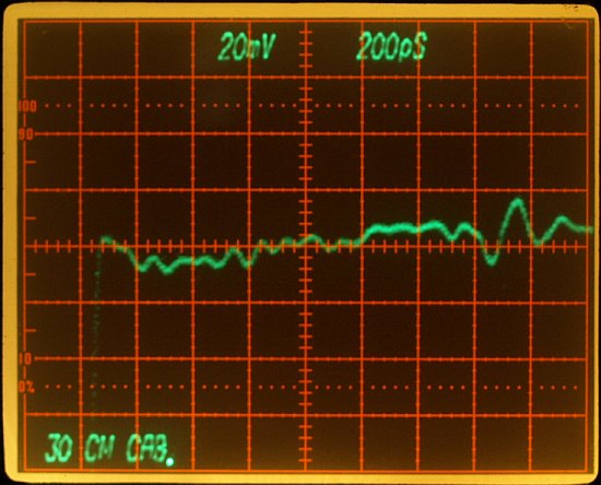
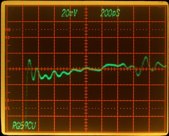
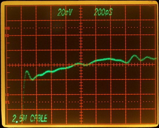
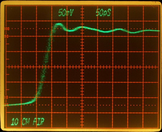
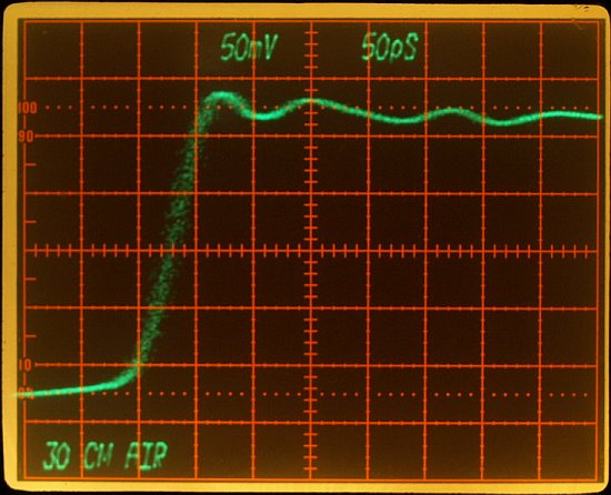
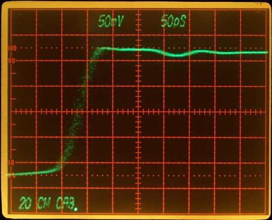
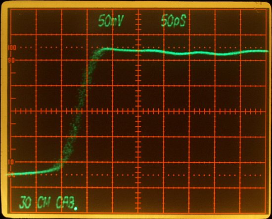
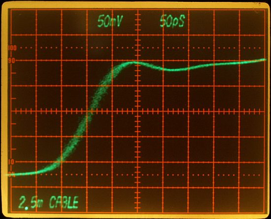
 Increasing line by adding a 10 cm airline
|
 |
 |
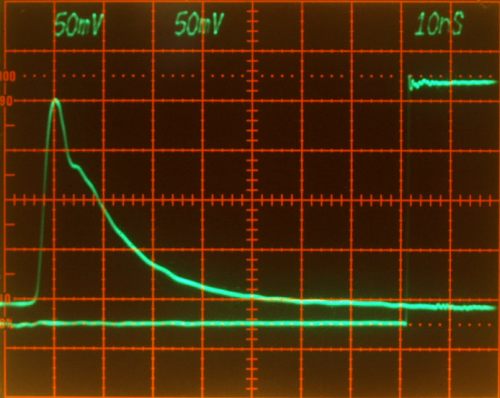
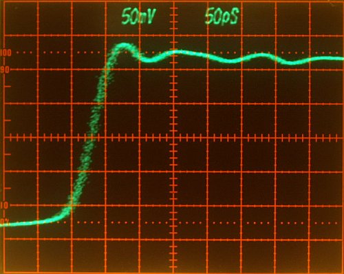
| Without
10 cm airline Displayed Risetime 50ps Displayed front corner aberrrations +/-5% |
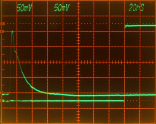
With
10 cm airline Displayed Risetime 50ps Displayed front corner aberrrations +/-5% |
| (note: ignore trigger instability in the right photo, this is a matter of adjustment only) | |
|
||
Comparing Aberrations:using a S-4 Sampling Head |
||
 |
 |
|
 |
 |
|
 |
 |
|
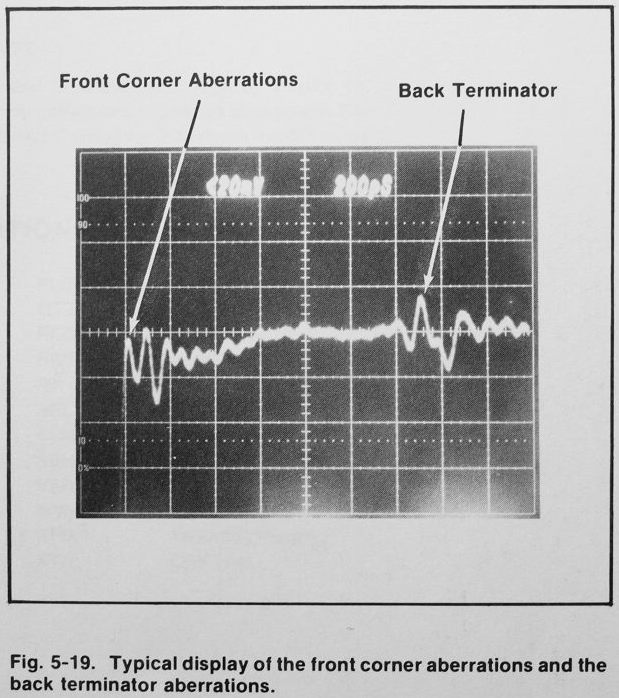
| Highest frequency contents
when using airlines. Result differs in front corner aberrations. Back termination damped with long cables. Start a Aberrations Slide Show (6 photos), (download exe file, scroll with mouse wheel or right left buttons) Comparing Risetime:using a S-4 Sampling Head |
||
 |
 |
|
 |
 |
|
 |
 |
|
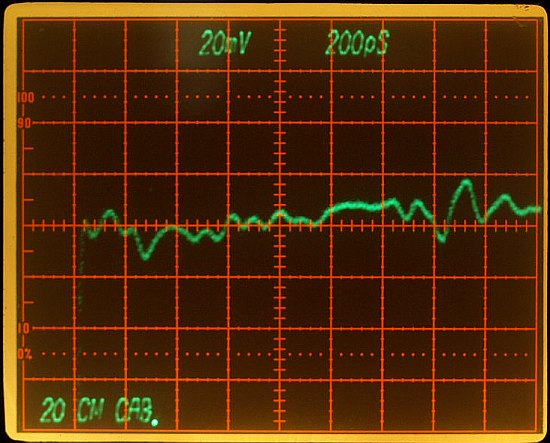
| Fastest displayed risetime
when using the 10cm airline. 45ps Risetime increase with length and dieelectric cable properties. In assumption the S-4 has a 20ps risetime, the 284 risetime can be recalculated: Sqrt(45*45*ps*ps - 20*20*ps*ps) approximately 40ps This risetime corrosponds to approx. 8.75 GHz Bandwidth (Bw=tr/0.35) Start a Risetime Slide Show (6 photos), (download exe file, scroll with mouse wheel or right left buttons) |
||
Results
ConclusionDas Heranarbeiten an Hochfrequenztechnische Problemstellungen fällt mit diesem Gerät wesentlich leichter, insbesondere entsteht damit ein echter Bezug zur Realität, weg von der schnöden alleinigen Theorie - wie oft schon haben Generationen von Elektrotechnikern (meist nur in ihren Studienzeiten) seitenweise mit Impedanzen und Reflektionsfaktoren herumgerechnet ohne eigentlich nicht wirklich zu wissen was sie da tun. Es wird gerechnet bis zum Sankt Nimmerleins Tag und nur selten der reale Bezug hergestellt - ein Trauerspiel. Die Erinnerung ist immer entsprechend vergesslich, abgesehen von den Berufs- und Amateur Hochfrequenztechnikern. Rechnen können viele, das ist nicht schwer, manche Formeln herzuleiten oder die schwierigen abzuschreiben auch nicht, aber sie zu verstehen oder gar was funktionierendes daraus zu machen das ist ein ganz hartes Brot, das geht leichter über eigene Erfahrungen. Natürlich den Hut ab vor hyperkomplizierter Mathematik - keine Frage - diese hat sich aber in der real erfassbaren Elektrotechnik hingegen als nur schwer realisierbar oder oft ziemlich gegenstandlos erwiesen; wer sie bei einem Problem nicht durch andere einfachere Lösungen zu vermeiden versucht macht schon den ersten Fehler - nur wenn es unbedingt so sein muss. Mit solchen Geräten hingegen kann es vorkommen dass man sich drei Tage am Stück damit beschäftigt um ständig seine Gebiete zu vertiefen. Eine ist eine wahre Freude 40 ps Impulse oder die Unterschiede zwischen einer 10cm und 30cm Luftleitung live erlebt zu haben. Solche Geräte (wenn nicht alt dann neu) sind eigentlich ein Muss in jedem anspruchsvolleren Elektronik Labor. The 284 is a nice source for testing fast transient response of amplifiers, sampling heads and a source for TDR, Time Domain Reflectometry measurements. Very helpful instrument for learning and working with high frequency. |
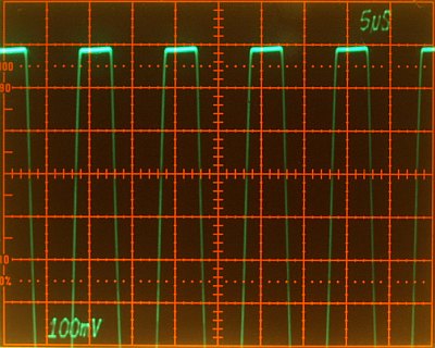
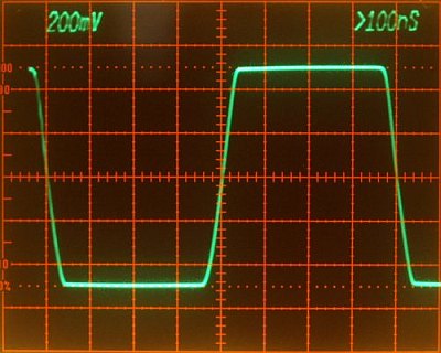
| J55 is the square wave output
going to the attenuator. Q35 and Q55 is a fast differential amplifier
in a comparator mode. Q55 base DC voltage set the output
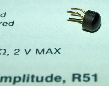
amplitude, Q35 base receives the AC signal frequency. Q35 and Q55 emitter held almost constant voltage, therefore a constant voltage across R38 and R39 cause a constant current. This currents flows current flows either through path R40 or R58 depending on the alternating Q35 and Q55 base potentials. The result is a square wave voltage across R58. Q35 and Q55 are responseable for the waveform quality. They are type 2N4258, this a ultra high speed switching transistor with a 700 MHz transit frequency. Q55 has to be a perfect fast switch, the DC Beta should be similar to the Beta under switching - if not - base current and collector current through R58 will will be different under AC and DC, resulting in a different DC and Switching mode amplitude. Q55 had only hfe=32 @ 50mA and Uce=1V, the datasheet specified hfe=min.30 under the same conditions. This transistor reached the lower hfe limit, this part getting old in a long life of operationg hours under high currents. Q35 and Q30 were also in a weak condition. A curve tracer is a very helpful tool. Q35 determines the waveform quality, especially for the squarewave risetime, but is not responsible for switching amplitude errors. What to do now?Unfortunately I don't have a new original transistor replacement on stock, I took another transistor and tried different types for Q35 and Q55. 2N3906 and BC Types - bad results - 100 ns Squarewave looked funny, transistor switching times seem to be too high or capacitances too high, I don't know in detail. 2N2907A - very good for the 10µs and 1µs low frequency square waves, due their higher beta, the rise time decreases a lot !, but the 100 ns Squarewave looked funny too. Now trying all other 2N4258 in the circuit (Q40 and Q30) on Q35 and Q55's place, taking the best one. Now I did experiments with different other transistors, the best overall result reached by replacing the Q55 with a 2SA1085 Type, the switching amplitude getting closer to the DC value and the waveform improved, unbelievable with such a slower type. Only the risetime decreased a little, but this doesn't matter, a flat square wave shoulder has more practical value, the former risetime peak almost disappeared. It was luck to find that type - it is a low noise, low speed transistor with high beta - high gain is good for amplitude accuracy - and it seems this transistor capacitance fit good in this application. At first glance theory it is the wrong transistor - but here the part worked ! |
 |
 |
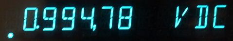
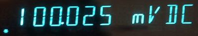
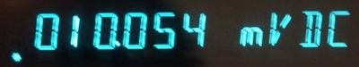
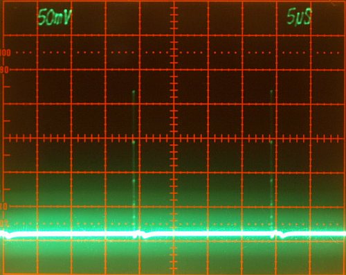
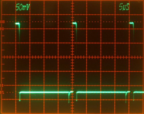
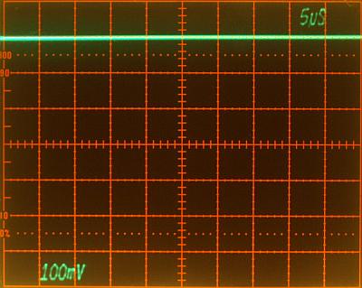
| with new transistors (DC level when Q35 removed) |
with new transistors (Q35 replaced in it's socket) Reduced by 10mV, with the old transistors 20mV. - improved, within specification now- |
 |
 |
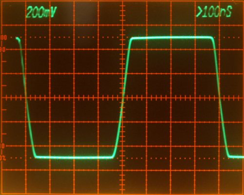
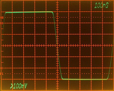
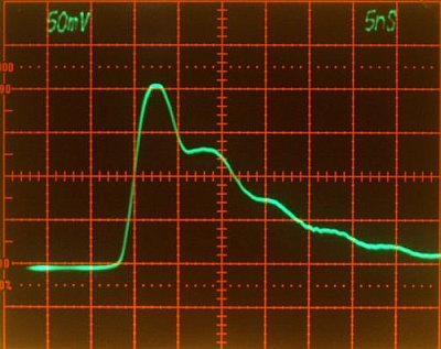
| with old transistors | with new transistors waveform and risetime remain unchanged - risetime is still an fault - |
 |
 |
| with old transistors | with new transistors waveform and risetime remain unchanged - risetime is still an fault - |
 |
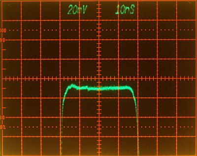 |
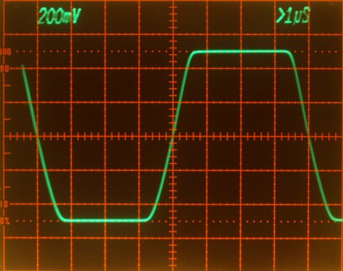
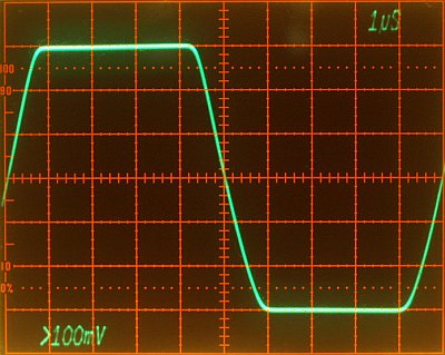
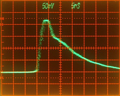
| with old transistors | with new transistors less overshooting, more flat - improved waveform - |
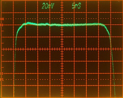 in detail |
|
 |
 |
| with old transistors Trigger |
with new transistors Trigger - trigger falling waveform improved - |
Q35 ==> Q40 (Q35 changed with Q40) Q55 ==> 2SA1085 Q40 ==> 2SA1164 Q30 ==> 2SA1164 Amplitude Calibration, I
canceled out the 10mV amplitude switching loss, by increasing the
adjusted DC by some additional mV, square wave amplitude seems to be
correct now compared to other generators. This experiment took me three
hours of testing different transistors, it not important what I did
here, but it was a interesting for me.
|
|