Experimente mit
Photos am Oszilloskope
Für messtechnische Zwecke wird ein schneller
Buffer benötigt, hierfür steht zuerst steht die
Betrachtung der
Signalquelle im Vordergrund. Als ein geeignetes Signal bietet sich ein
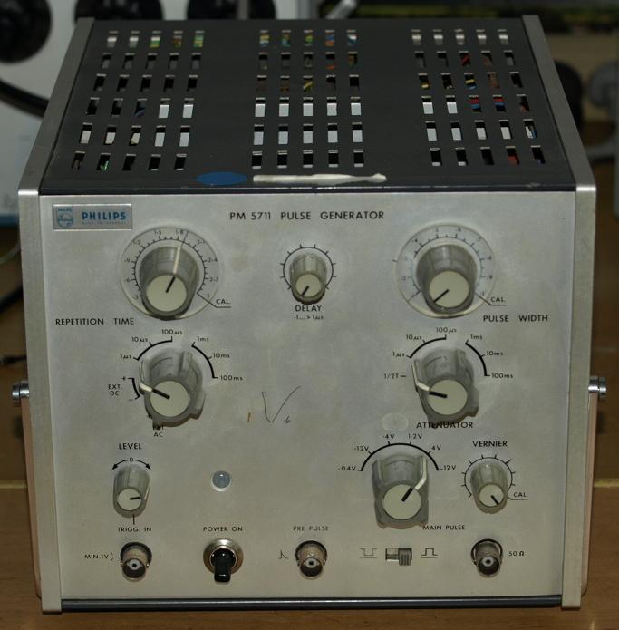
Pulsgenerator an.
Pulse generators are a good choice as fast buffer test signal.
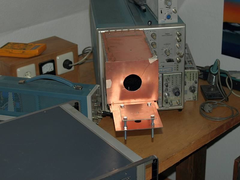
Als Ausstattung
kommt hier zum Einsatz:
7904 ein 500 MHz Oszilloskop
7A19 ein 50 Ohm 500 MHz Verstärker
7A26
ein 200 MHz Verstärker
7A16A
ein 225 MHz Verstärker
7A18
ein 75 MHz Verstärker
7A92A eine schnelle Zeitbasis
Halterung für die Kamera
und als Testobjekte die Pulsgeneratoten:
PG501
1917A
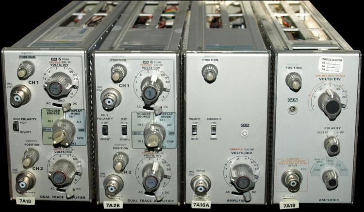
amplifier under test
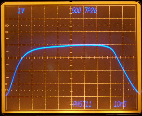
Pulsgenerator 1917A:
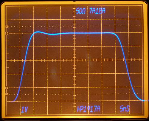
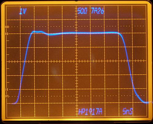
75 MHz
200 MHz
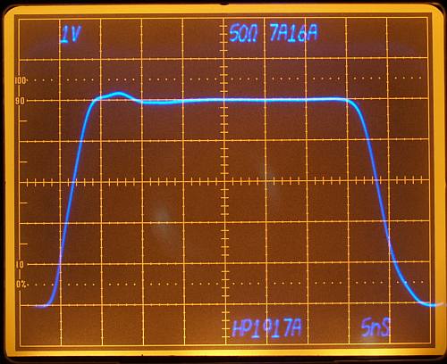
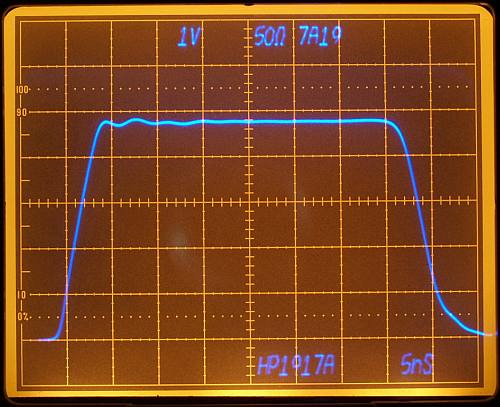
225 MHz
500 MHz
Some ringing caused by cable.
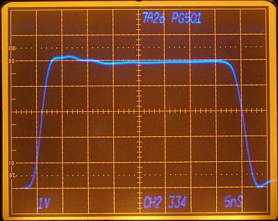
Pulsgenerator PG501:
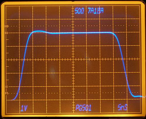
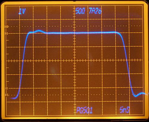
75 MHz
200 MHz
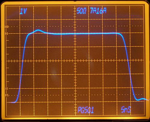
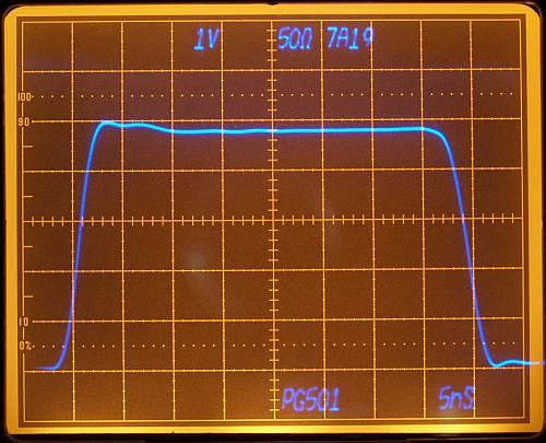
225 MHz
500 MHz
Alle Verstärker außer dem 7A19 wurden im Vertikal
Gain so
eingestellt, dass das Signal die fünfte vertikale Division
trifft.
Jetzt die Frage welcher Verstärker zeigt das der
Realität am
nächsten kommende Bild? Für schnelle Signale kann man
nicht
genug Beandbreite habe. Die Kalibration des Frequenzganges der
Verstärker im Hochfrequenzbereich ist eine anspruchsvolle
Sache,
die gute Generatoren, Fingerspitzengefühl und ausreichend Zeit
erfordert. Diese Verstärker hier werden an einem langweiligen
Abend irgendwann mal wieder auf HF Vordermann eingestellt. Beim
normalen Betrieb fällt das nur wenig auf. Die Messungen
benutzten
alle die gleichen Oszilloskop Einstellungen und die gleiche Zeitbasis.
All amps except the 7A19 are adjusted in gain to be in line with the fifth
vertical Division for a better comparison. Which is the right
diagram? Hard to say, for such fast transient signals it's not a
mistake having much bandwidth. Very important for such fast
signals, the amps should have a good high frequency calibration.
Calibrating high frequency step response is not an easy task,
require good generators and time. I didn't calibrate the Plug-In's
since a long time, a task for a boring evening. Measurement
used
always same mainframe slot, same scope settings and time-base.
Pulsgenerator PG501
an sieben verschiedenen 7A26 Verstärkern
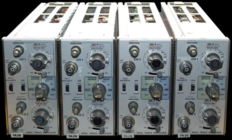
Für den folgenden Versuch wurden
vier gleiche 7A26
Einschübe
am gleichen Testsignal nacheinander betrieben. Eingeblendet ist immer
der jeweilige Kanal CH1 oder CH2 und die letzten drei Digits der
Seriennummer. Alle Messungen betrieben mit 50 Ohm
Abschlußwiderstand und 15cm Koaxialkabel. Die Lönge
und
Qualität des Koax Kabels bewirkt nur leichte
Änderungen. Viele Leute behaupten immer im Standardsatz
beispielsweise: "100 MHz Oszilloskope sind völlig ausreichend", in
den meisten Fällen haben sie auch Recht und dem schließe ich
mich auch an. Aber in solchen Fällen wenn es wie hier darum
geht die ansteigende Flanke des Pulsgenerators
wahrheitsgemäßer zu betrachten, da hätte man am
liebsten 1 GHz aufwärts oder einen funktionierenden
Samplingeinschub, der mich heute mit einem Wackelkontakt begrüßte und inspiziert werden muss.
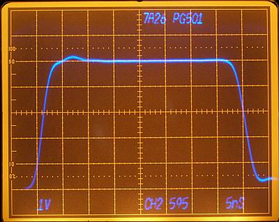
This experiment use seven
different 7A26 Plug-In amplifiers with the same
test signal. Shows how different a fast test signal
can look even with the same type of test equipment. The numbers e.g. 595
or 566 indicate the last three digits serial of the number plug-in.
CH1
or CH2 indicate the channel. All measurements made
with 50 ohm termination and a 15cm cable. Normally 100
MHz bandwidth good enough for most applications. In case of
viewing a fast rising step response better use 1 GHz bandwidth or even
more, unfortunately my Sampling plug-in needs an inspection.
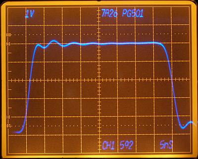
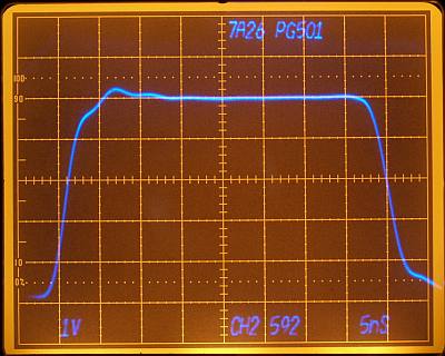
592 CH1
shows ringing, need recalibration
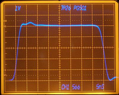
566 CH1
could be a little undercompensated,
but has same character as the faster 7A19 measurement.
592 CH2
seems to be overcompensated, needs fine adjustement
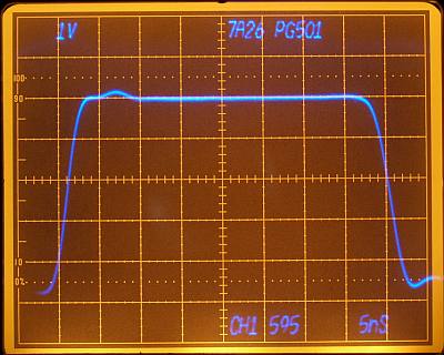
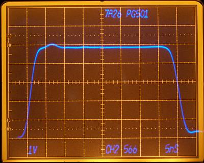
595 CH1, CH2
and 566 CH2 show
a good adjusted step response.
334 CH1 don't work
Difficult, without knowing the real input waveform.
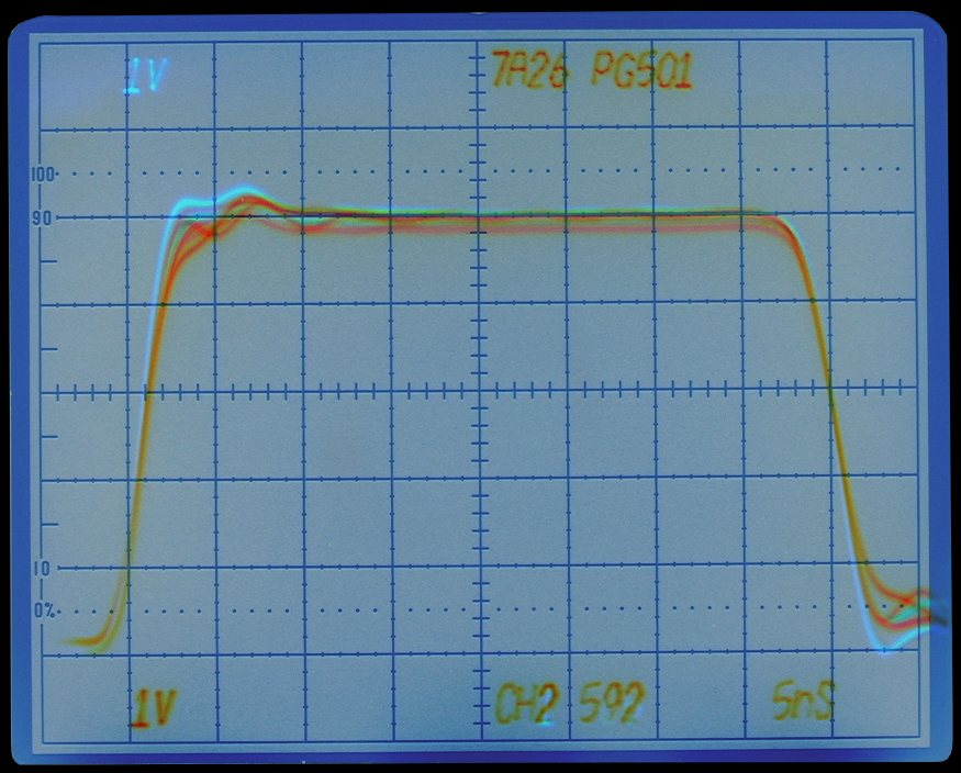
All seven 7A26 channels added together into one picture using software. Without the camera
holder it would be almost impossible creating such a picture.

Triple Channel Spring Oscilloscope
Ein Zeitsprung um
ettliche Jahre
let's jump forward for some years in oscilloscope development using a
digital scope for chart comparison.
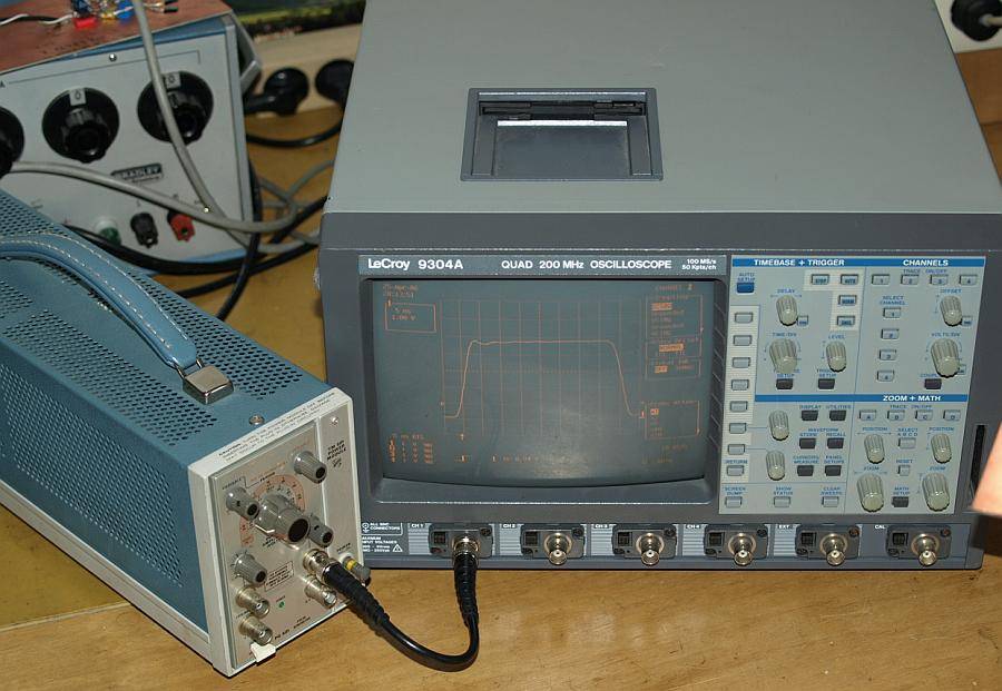
For this measurement I took from my junk-room a quad
channel 200 MHz 100MS/sec oscilloscope, stores TIF waveforms on a 3.5 floppy disk. The scope works electrically very
fine, the hard things are pressing
always many buttons changing simple operation like
trigger
or AC-GND-DC coupling.
Waiting for the day a digital scope comes with:
4 buttons for vertical
4 buttons for coupling
4 buttons for trigger
4 buttons for vertical offset
4 buttons for horizontal offset
basic readout information written large enough, no need for classes
less important readout information should written small
one time pressing or switching only ---> successful new setting
|
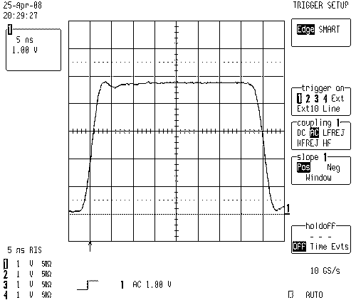
Channel 1
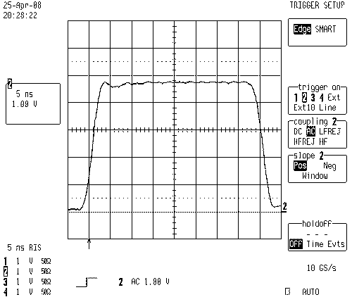
Channel 2
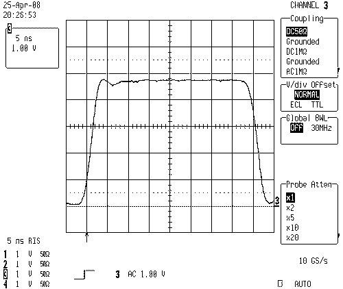
Channel 3
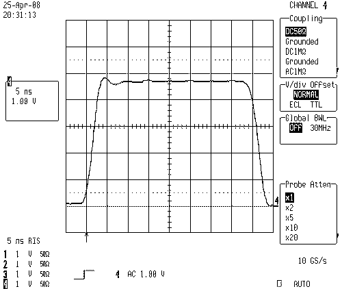
Channel 4
All four channels overlayed with software. In all four measurements
same trigger and offset settings. Similar step response on all four
channels, really a pretty scope. Channels are delayed to each other in the same order as the channel
numbers.
CH1 green
CH2 purple
CH3 grey
CH4 red
????
Coincidence?, I don't know what causes the delay. Do you know? - Please tell me.
Jetzt wird noch einer probiert
test of another generator
Steht wieder im Keller.
Back to the basement.
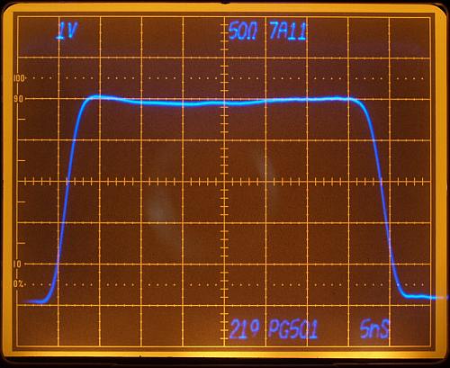
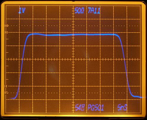
Test zweier 7A11 Verstärker
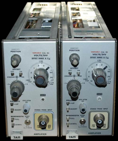
Die Tastköpfe lassen sich heruasziehen.
Measurement with two FET
7A11
Amplifier with a low capacitance input. Sometimes very usefull
operating with such a low capacitance input impedance. Input was
terminated with 50 ohm direct on the probe input plus the 15 cm cable.
Number 219 and 548 indicates the three last serial number digits.
These measurements helps me choosing the plug-in at any time.
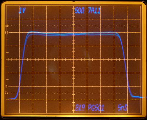
Both 7A11 photos overlayed with software. They differ slightly in
gain, easy to readjust. This FET plug-in shows a nice step response.
Remember, a 7A26 with 22pF input capacitance already leads via
Xc=-1/2*PI*f*22pF to only 14 ohms (at 500 MHz).
Coaxial cable RG58 about 25 to 30 pF per feet.
Every 50 ohm conncetor add some pF.
No cable is still the best cable, but be carefull many instruments are
calibrated together with a defined cable length, read instruction
manual.
That generator here would be wonderful with a higher output voltage.
Measurement continues

Impressum
und Haftungsausschluss