This scope had a fault. The power
supply had a short circuit with a blown primary fuse. In many cases a
blown fuse can be a terrible fault. Before the scope run for
approximately 1 hour with four Plug-in under an ambient temperature of
more than 30°C. After changing many times the Plug-in (I always
switch of before changing) a loud Bang and Bum and the fuse was blown.
Nowadays I put a room fan behind the power supply, always very
cool.
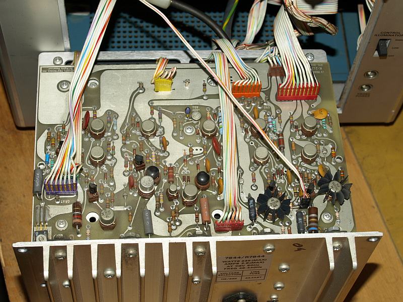
photo shows the linear voltage regulator board, consists of +130V, +50V, -50V, +15V, -15V und +5V.
Removing AC-cord, Plug-ins out and remove the power supply from the
mainframe. Take care when working with this switching converter power
supply, the main capacitors storing a high charge and the rectified
dangerous line voltage, wait at least until the small gas discharge
bulb had stop blinking, then the capacitor voltage is under appr. 80
volts. When reaching that small voltage discharge the caps with some
hundred ohms totally. Follow the service manual for all safety hints.
Use only an AC-line isolated variac transformer when working with the
open power supply. Take care also for the CRT High Voltage, this
glass-vacuum isolated capacitor stores the energy even for many days!
dont't think: "I switched off the scope yesterday, now I am safe" your
are not !!!, the voltage is still high enough for a very long spark. Be
extremly careful when you remove the white High Voltage plug, discharge
it on the chassis, but be careful again when pull of both plugs - keep
a respectful distance to any electronic part when the jack is open!
otherwise the spark will destroy parts on the PCB. When measuring on
the PCB use a 1:100 probe with a specified voltage much higher than the
line voltage, for your own safety.
Unfortunately the cables from the power supply to the mainframe
are short, but long enough to search for errors. I guessed the
fault is located somewhere in the primary circuit in the Inverter PCB,
this means the power supply should be separated from the mainframe and
semiconductors must be checked.
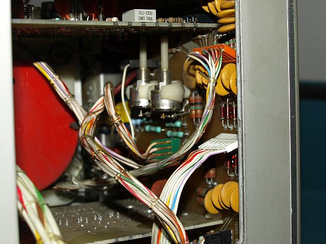
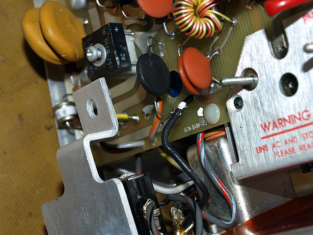
Some cables from the power supply are
spreaded wide in the instrument, here the Z-axis and CRT circuit.
Before removing the connectors, write down which connector fits where,
it is helpful for reassembling, take care for connector polarity. A
torch is a usefull helper. The black dust on the wires energised by the
electrostatic force of the HV in the CRT circuit, nominal -2960 volt on
the vertical mounted PCB, be careful in that area. Remove all black
dust with e.g. Isopropanol and a cotton cloth.
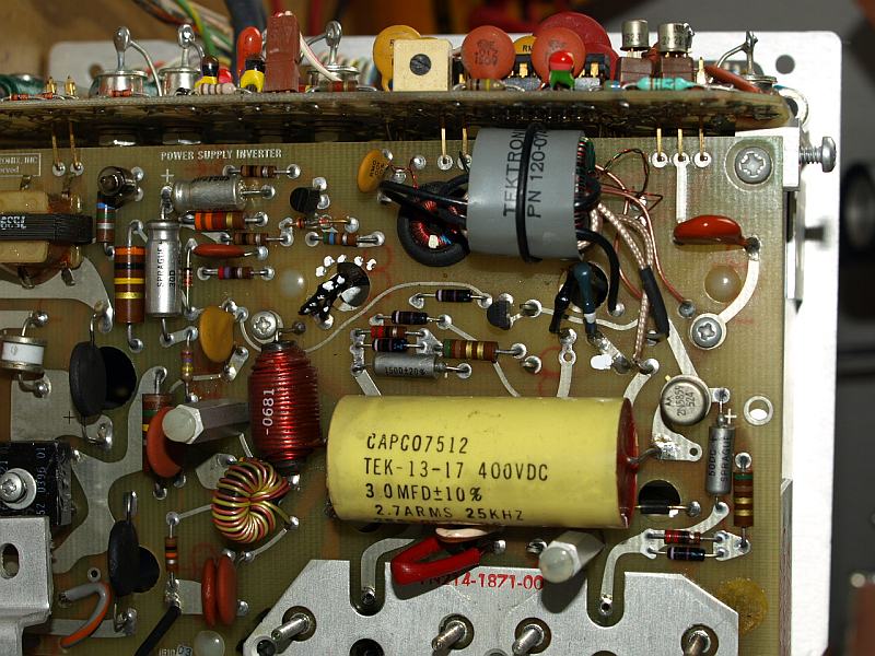
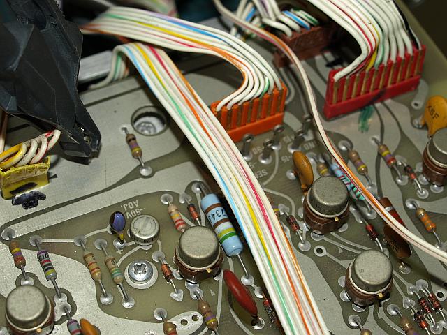
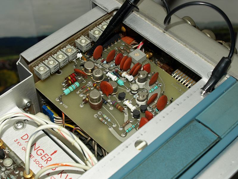
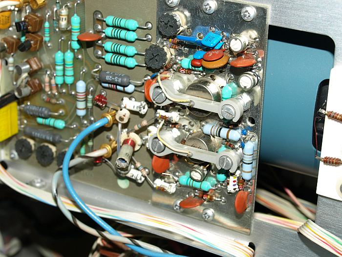
This is the Power Supply Inverter
circuit, AC-line voltage rectification, generates the rectangular
supply voltage for the high frequency transformer. This DC/DC Converter
acts as LC series resonance tank, L=1mH and C=0.03µF resulting in
a 29 kHz natural frequency. Depending on line voltage amplitude and
secondary load varies the pulse width and switching frequency. This
series resonant circuit has a good efficiency and approach sinusoidal
primary current, a good precondition for a well secondary rectifiying
with low ripple. Clean output voltages are a must for a precision
oscilloscope.
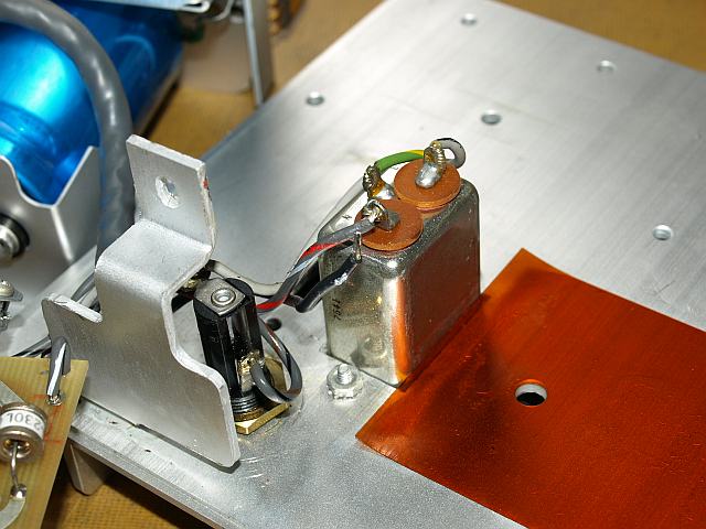
On the photo top right the transformer T1230 for supplying the
antiphase switching transistor base current (Q1234 and Q1241), mounted
on the bottom aluminium heat sink. Top left side, there is the 50/60Hz
line voltage sense transformer T1208, supplying the oscilloscope with a
"LINE" trigger signal. Middle, left the small white part a gas
discharge overvoltage spark protection preventing from excessive high
line voltage by blowing the primary fuse.
Middle, right the TO-case transistor Q1246 called the "Over
Voltage Stop Circuit" a componemt of the safety concept. This Q1246
were destroyed togehter with a 22 ohms in the base of a main
swichting transistor.
Left side from T1230 the small round T1235, supplying the DC-DC
Controller U1275 with a dual low power supply voltage, the T1235 has
also a overcurrent protection function.
Left AC line diode bridge, a common
mode choke, another gas discharge protection, right side aluminium
heat sink for the bipolar switching transistors. Before you reach the
Inverter, some wires must be resoldered from the PCB, note everthing
detailed before removing anything.
Unfortunately both switching transistors Q1234 and Q1241 were defect with an internal short circuit.
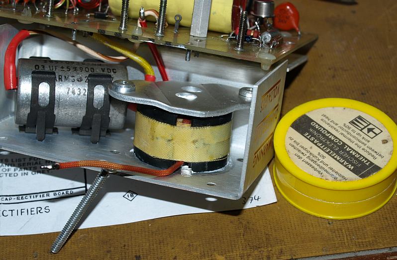
AC-line filter and primary
fuseholder. Isolation material for the aluminum hest sink of the
switching transistors. Normally you should not remove this small heat
sink, because reassembling need some special care. Be carefull that
both surfaces between aluminium and isolating-foil are very clean,
apply new heat-conductive paste - no small foreign particle between
foil and metall, very dangerous, possible isolating damage .
After a careful reassembling, torque the screws softly and alternating.
The Service Manual write: "dont remove that heatsink" - but here it was
a must.
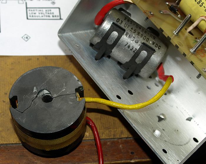
Another broken part, the 1mH Series
Resonance Coil L1237 and the Series Resonance 900V foil capacitor
C1237 (not faulty). The core was broken, some small peices were
spreaded in the power supply, but the choke has still 1mH on the
inductance meter.
Leaving that part in the power supply would be dangerous, I don't know
the inductance value under load current, never know what happens when
the crack increase, a further inductance loss can results in an
excessive current destroying the power supply again - too risky -
replaced by another 1mH choke taken from a old cannibalized 7904 powe
supply, that choke were a little small, but should work. If you don't
have a spare part, make your own 1mH coil. I think any LF power choke
of a similar size should be ok for this purpose.
I really don't know why the choke is broken, too hot, mechanical stress or both?
Reassembling the choke, use
heat-conductive crease and torque the screw again carefully, not too
much will result in mechanical stress. Ferrit material is very hard and
brittle dangered by too much torque and small parts between the
mounting gap. This screws can be secured by a loctite when using a low
torque.
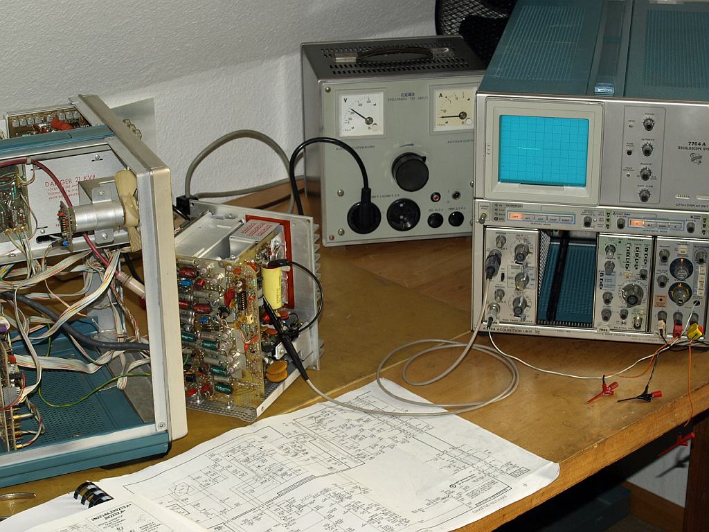
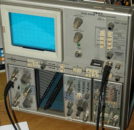
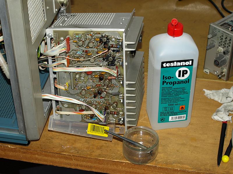
A typical repair place with AC-line
isolating variac, test oscilloscope, curve tracer, probes 1:10 and
1:100, Service Manual and transistor datasheets. Having a Curve Tracer
is a very useful tool when repairing instruments, saves so much time
and gives a high level of assurance of part function. With a simple DMM
transitor tester function you won't find every defect transistor, some
transistors are ok with the DMM tester but they are showing funny
curves on the Curve Tracer.
No further faults could be located in the Inverter - Reassembling -
Power ON - nothing happened - disappointed. What's the matter?
Something wrong with the high frequency transformer, oh no, this would
be a terrible fault. Reaching the inner double shielded primary winding
what a bad job to do, winding everything new, no thanks. (most terrible
winding would be the inner HV winding, catastrophe when leakage)
One hour later I was luck because I found a small defect 2N2222A Transistor near the U1275 Controller.
left a new transistor, right a fault one
I assume the high short circuit currents caused the defect switching
transistors. Through the high currents flowing in T1230 may be on teh
secondary developed a high voltage destroying Q1252. Q1254 were lucky
to be protected by C1259 with 2µ2. Also Q1246 could be destroyed
thru the 4 windings of T1230, even R1240 were fault. I don't know the
real reson which part destroyed which.
List of fault parts
Q1234 NPN Power
Transistor
Q1241 NPN Power Transistor
R1240 Basiswiderstand 22 Ohm
Q1246 NPN Transistor vom Over Voltage Stop
Q1252 NPN 2N2222A Kleinsignal Transistor am U1275 DC-DC Converter
Controller
L1237 Serien Resonanz Induktivität 1mH
Calibration Start
A full calibration makes sense after
a large repair or after receiving a new instrument, this was my case.
Most oscilloscopes receiving new having a calibration within
specification, some are teribble, but ones with excellent status are
seldom - the design is not the problem. It takes time after many years
of use such a full calibration, time is something seldom for many
companies, they sell it, hobbiests are lucky about that.
Necessary equipment, if you have two
Calibration
Fixtures
it is a luxus still today , decades ago it was a sign for a good
status. Without the calibration fixtures it takes much more time.
Another nice item for the horizontal part is a
Time Mark Generator. For amplitude calibration a
Sweep Sinus
Generator for adjusting the vertical amplifier step response
Rechteckgenerator or e.g. a 284.
Another time consumption, searching the test points in the manual.
Calibrating this 7844 took me 10 to 15 hours, I guess when used for it
3 hours, Consider with a Dual Beam many calibration steps must done
twice due the two guns.
The following series show some photos of the calibration, I didn't took
for every calibration step a photo, this would be too much.
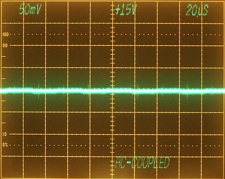
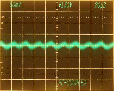
Measure the voltages on the testpoints, connect the probe on the
recommended points. Use a DMM for DC and also check the voltages with a
AC-coupled test oscilloscope for ripple.
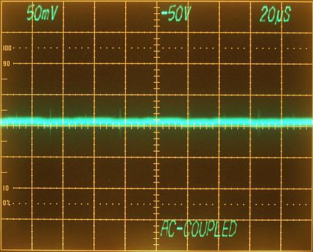
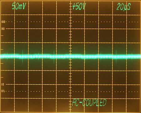
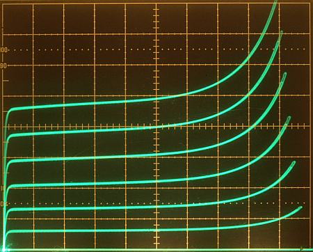
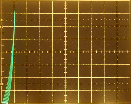
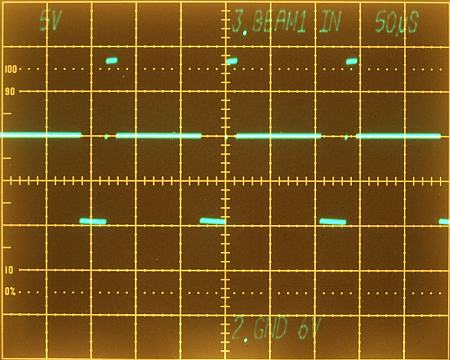
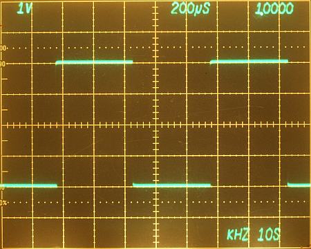
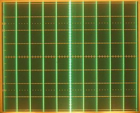
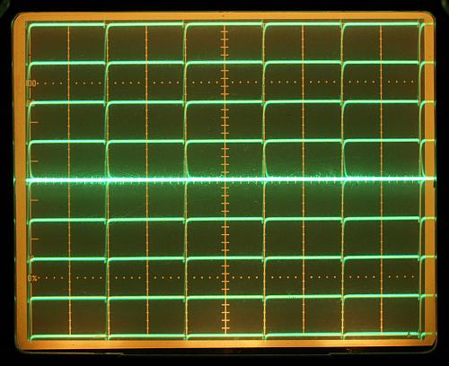
Power Supply Output Voltages AC-Coupled
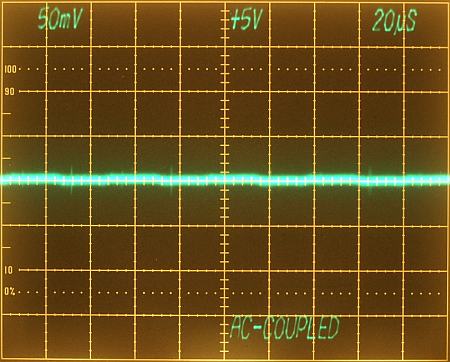
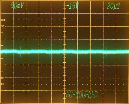
Power Supply Output Voltages AC-Coupled
Power Supply Output Voltages AC-Coupled
Calibration CRT photos:
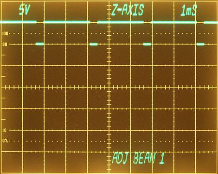
Chapter B. Z-Axis and CRT Display
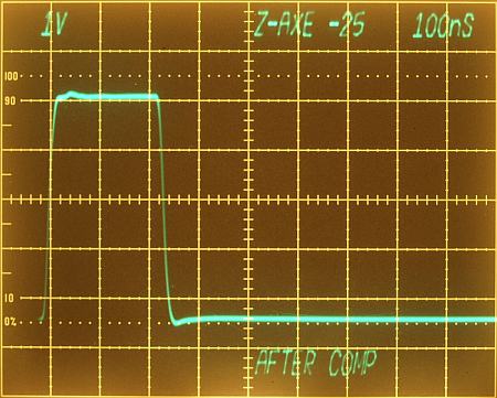
1. Adjust Z-Axis (R1180), set Beam 1 Intensity for a 5V square wave.
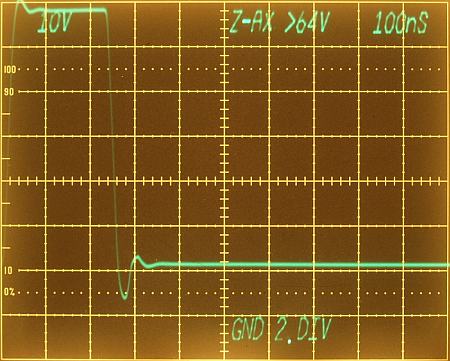
Chapter B. Z-Axis and CRT Display
2. Adjust Z-Axis Beam 1Transient Response (C1168, R1168, C1172) , adjust Beam 1 Intensity for square wave >=64V.
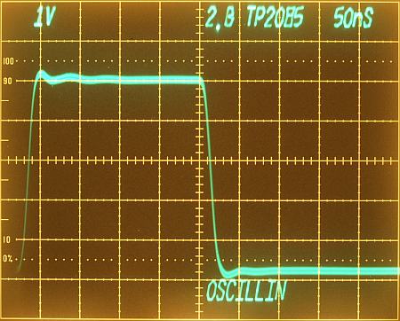
Chapter B. Z-Axis and CRT Display
2. Adjust Z-Axis Beam
1Transient
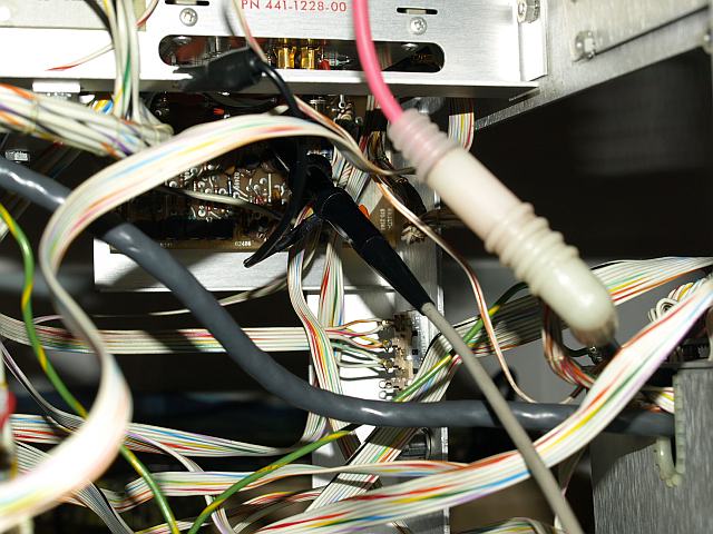
Response (C1168, R1168, C1172) at TP1185 , Beam 1
Intensity amplitude reduced by 25% reduziert wurde and adjust for
best step response with high rise time and lowest aberrations. In
this case it was a good idea readjust the step response. Fix the probe
very short, if you don't do oscillations can occurs. Before turning the
potentiometer and trim-capacitors mark their original positions with a
small pen, gives you a chance going back to the old settings - you
never know if you reach at all better setting than before and when
there is a chance going back you it's your luck.
Chapter B. Z-Axis and CRT Display
3. Adjust Intensified Z-Axis Beam 1 (C1168, R1168, C1172) at TP1185.
Chapter B. Z-Axis and CRT Display
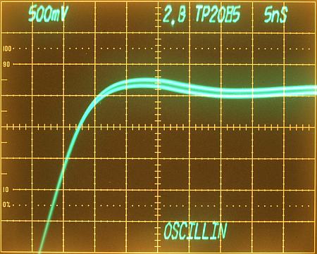
5. Adjust Z-Axis Beam
2Transient
Response (C2068, R2068, C2072) at TP2085 , target best step response.
Oscillation occurs due bad probe connection, difficult on this PCB,
deep inside the scope.
High Voltage from the multiplier in the power supply.
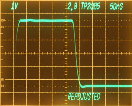
Setting of Z-Axis Response Beam 2 after readjusting.
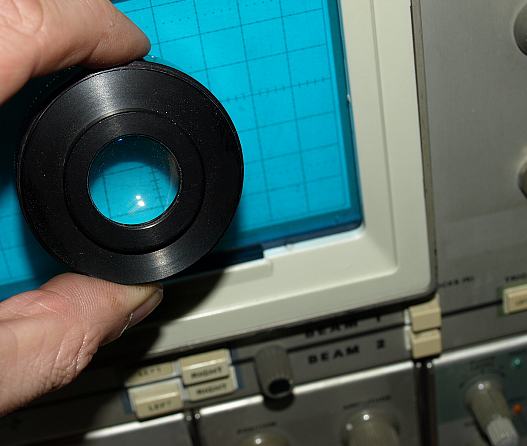
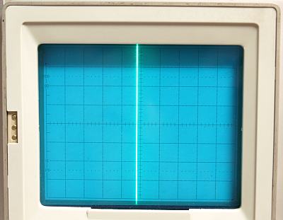
Adjusting the CRT geometry is a
demanding procedure, in one step it was necessary adjusting the beam to
a point round as possible, lenses helped me for a better adjustment.
Chapter B. Item 17B Adjust Beam 1 and Beam 2 CRT Centering.
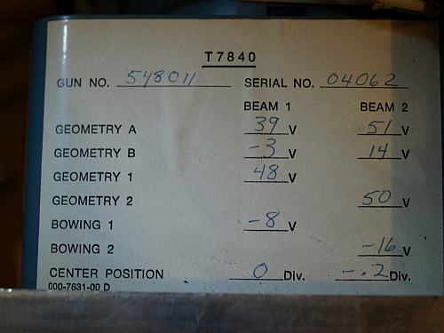
On a sticker on the CRT shielding the original CRT geometry settings. In one step it is necessary to check the given values.
Chapter B. Item 17B Adjust Beam 1 and Beam 2 CRT Centering.
When it's correct adjusted the beam should looks like here (-0.2 DIV), it was correct no readjustment necessary.
Chapter C. Calibrator and Output Signal
There are many possibilities adjusting
the amplitude and frequency of the calibrator. I followed for the
amplitude the manuals instruction, for the frequency I used a
7D15 Counter.,
Chapter C. Calibrator and Output Signal
Everything seems to be ok, amplitude and frequency.
Chapter E. Horizontal System
2. Adjust Beam 1 Horizontal Amplifier Gain (R4820)
For this adjustment is a
Calibration
Fixture
a wonderful help. The calibrated step generator allows a precise
adjustment of the vertical and horizontal gain. If you adjust all of
your 7xxx scopes with the same gain, every plug-in is changeable
without a necessary recalibration of the front "Sweep Cal" or "Vertical
Gain".
Chapter G. Vertical System
Adjusting the vertical amplifier response is the most difficult
calibration step and one of the most important ones. Determines
bandwidth and quality of the step response. the calibration fixtures
allows an easy gain adjustment and step response, adjsuting for a flat
response you'll time, after 20 minutes of trying you'll understand
which trimmer causes which effect. For the vertical amplifier it is
very important to mark the old trimmer positions - to go back to the
old setting if necessary. Fortunately the settings of the step response
should remain stable for many years, may be for instruments life time,
I don't know.
Chapter G. Vertical System
vertical gain well adjusted
Cleaning the oscilloscope
Cleaning make sonly fun after a
sucessful repair, when cleaning first followed by a unsucessful repair,
what a horror, I don't think about that.
Cleaning with Isopropanol (removing again the PCB - no thank you)
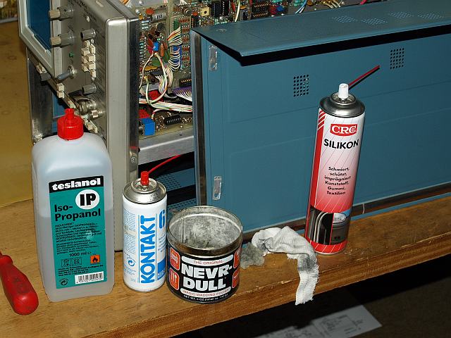
My tools Isopropanol, contact cleaner, metal polish for the
non-anodized aluminum parts and silicone oil protecting paint and
plastic knops, give everthing back a nice shine.
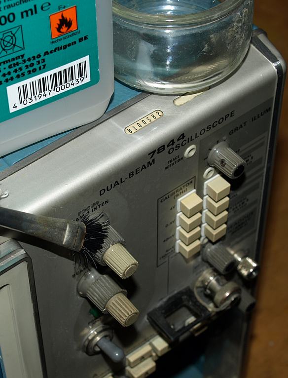
Cleaning the knops with Isopropanol and a brush. I don't like dirty knobs with other people dust.
Some metal parts can be polish for a
very nice shining. Unfortunately oscilloscopes without scratches are
very seldom, most users in companies didn't take much care for these
expensive instruments. Many people were never interested in keeping
their equipment clean, they took care on the weekend for their
cars but not for the equipment. Nowadays it getting even more worse.
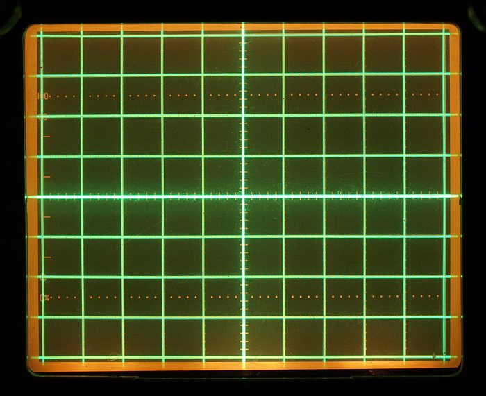
I'am very satisfied with this geometry of a Dual Beam, wonderful, only
small abberations from the ideal. After some weeks use get the scope a
more detailed CRT geometry readjustment. In this phot one beam draws
the vertical lines the other beam the horizontal lines, setting the
beams vice versa changes also vertical wiht horizontal.
Don't think all oscilloscopes having a good adjusted geometry, many
people don't know the condition of their geometry. Without owning
fixtures use the grounded amplifer for a horizontal line check and
adjust a time base in the vertical compartment for checking the
vertical lines.
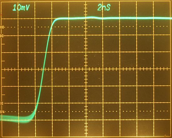
For example this photo shows the
PG506 step response of a
7A26
amplifier adjusted on this oscilloscope. Took approxiamtely 20 minutes
for a flat adjustment. Some improvements are still possible. This
amplifier and mainframe combiantion has a specified rise time of 2.2ns,
the result is well within the specification. I adjusted for a flat
response with less abberations, minimum rise time wasn't the target, a
gain of additional 200ps rise time would be possible, but the price for
it an overshooting.
Outlook:
I like the 7844, this socpe has a good change to be my Number One for
genral purpose working. Using two fast bright beams it is very
comfortable. I don't want to talk to much about what you can do with a
Dual Beam in comparison with a Dual Trace, there are not many
applications where a Dual Beam is really necessary - but one thing for
me getting important - it is very comfortable !
Independent beams,
Two independend trigger systems, e.g. Beam 1 with 20ms/DIV and Beam 2 with 1ns/DIV at the same screen, try it with a Dual Trace.
A Dual Beam must not share the intensity time with another
channel, a Dual Beam with both beams on 1ms/DIV still looks
pretty, on a Dual Trace the screen already starts flickering.
Trace on Beam 1 and Readout on Beam 2, a Dual Trace must share the readout always.
If you don't like "ALT" and "CHOP" Buttons, try a Dual Beam.